
Ship stability and stowage · Level P3 · 5 parts · about 19 min
Loading, ballast and the stowage plan
5 short parts: Stowage plan · Deadweight · Ballast · Loading computer · Departure. Each part explains the idea, then gives the points to remember, the common mistakes, a worked case and a practice question; the Academy unit adds all 29 check questions.
1 · Stowage plan
The stowage plan: where each cargo goes and why
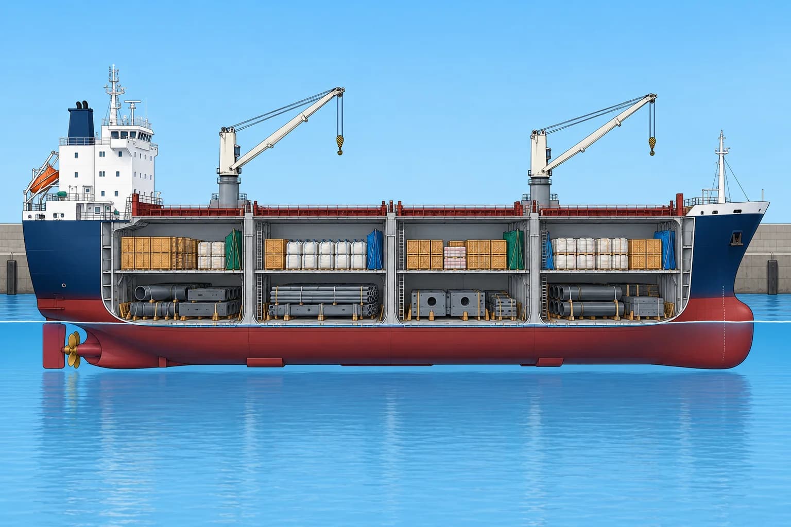
A stowage plan shows where every cargo lot sits aboard. A good plan keeps the ship safe, the cargo sound and each port’s cargo easy to reach.
What the plan shows
The stowage plan, or cargo plan, is a drawing of the holds and decks showing every lot: port of loading and discharge, weight, quantity and position. On a container ship, a bay plan locates each slot by bay (along the ship), row (across it) and tier (height). On general cargo and bulk ships it is often a hold plan, a profile and a plan view of each hold. The chief mate prepares it; on cargo watch you load to it.
Port rotation
The port rotation is the order of the ports. Where compatibility and safety limits allow, stow cargo for the last port first and deepest, and cargo for the first port on top or nearest the hatch. Avoid overstowing: cargo for a later port sitting on top of cargo for an earlier one. Then you must restow, move cargo to reach what lies below, which costs time and money and can upset stability and hull stresses mid-voyage.
Weight and stability
Heavy cargo low keeps KG, the height of the centre of gravity above the keel, low. Too much GM, the metacentric height that measures initial stability, makes a stiff ship: quick, violent rolls that strain lashings. Small positive GM makes a tender ship: slow rolls and weak initial righting. Distribute weight along the ship for suitable trim, the difference between forward and aft draughts, and hull stresses within the loading manual’s limits. Balance port and starboard weights to avoid list, a sideways lean.
Separation and space
Keep cargoes that harm each other apart: wet from dry, smelly from food, dusty from clean. Separation of lots of the same cargo, by nets, sheets or paint marks, stops them mixing at discharge. Dangerous goods follow the IMDG Code segregation rules (see Cargo securing). The stowage factor is the volume one tonne of cargo needs, in m³/t; it tells you whether a hold fills by weight or by volume first.
Planning order
Work in this order: what the ship may carry (load line, deadweight), what the cargo needs (compatibility, segregation, access, port rotation), then stability and strength. Run the plan on the loading instrument before loading starts and again for every change. Keep the final plan on the bridge: it is your reference for checks during the voyage and for the next port.
Key figures
- Stowage factor (SF)
- Volume per tonne of cargo, m³/t
- Tonnes a space takes by volume
- Space volume ÷ stowage factor
- Example
- 6,000 m³ hold, SF 1.5 m³/t → 4,000 t, if weight limits allow
- Last port’s cargo
- Normally lowest, where compatibility and safety limits allow
- Bay plan
- Bay, row and tier of every container
Remember
- The stowage plan shows every lot’s port, weight and position; you load to it on cargo watch.
- Plan discharge access; last-port cargo normally goes deepest, subject to compatibility, stability and strength.
- Too much GM gives quick, violent rolls; too little gives slow rolls and weak initial righting.
- Keep incompatible cargoes apart and separate lots of the same cargo.
- Check the plan on the loading instrument before loading and after every change.
Common mistakes
Wrong: Put all the heaviest cargo in the bottom of the holds; the more GM the better.
Right: Too much GM gives violent rolling that breaks lashings and damages cargo. Aim for the GM the booklet and the voyage need, not the maximum.
Wrong: Load whatever arrives first into the nearest empty hold.
Right: Follow the plan and the port rotation. Random loading leads to overstowed cargo, restows and unplanned stresses.
Worked case
Loading is under way when the terminal offers 300 t of cargo for the first discharge port, ready now. The only free space is the bottom of No. 2 hold, under cargo still to come for the last port. What do you do?
Show the answer
Do not load it there without the chief mate’s decision: it would be overstowed and need a restow at the first port. Report it. The chief mate can rearrange the plan, for example by holding the cargo until a suitable space is free or using another hold, and must recheck stability and stresses on the loading instrument for the new plan.
Practice question
You carry cargo for ports A, B and C, in that order. Looking only at port rotation, which lot goes in first and lowest?
- Cargo for port A, discharged first
- Cargo for port B, discharged second
- Cargo for port C, discharged last
- Cargo for whichever port loads first
Show the answer
Answer: C. Cargo for the last port goes in first and deepest, so cargo for earlier ports can be stowed above it and discharged first.
2 · Deadweight
Deadweight: how much cargo can you load?
Cargo = allowed displacement − lightship − all non-cargo deadweight. Check load line, voyage limits, volume, stability and strength.
The terms
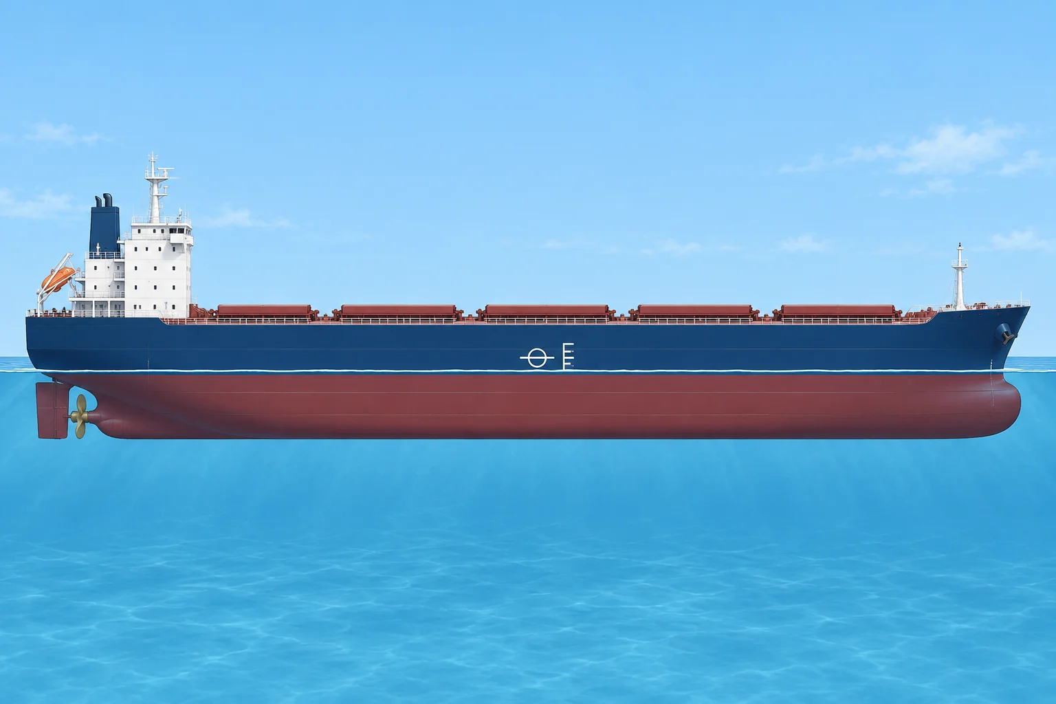
Displacement (Δ) is the ship’s total mass in tonnes. Lightship is the empty ship with machinery and system liquids, as approved in the stability booklet. Deadweight (DWT) is everything else: cargo, fuel, fresh water, ballast, stores, crew, personal effects and the constant. The constant is residual weight left after subtracting approved lightship and all separately accounted weights from surveyed displacement. It can include unrecorded sediment or extra gear. Use the latest verified value from a cargo-free draught survey.
What limits displacement
The load line for the zone and season limits displacement (see Load lines). Port or canal depth, berth limits, hull strength and stability may impose a lower maximum. Use the lowest applicable maximum. Check air draught, the height above water, separately: floating deeper usually reduces it. Bridge clearance may require a minimum draught, so the lightest passage condition may be critical. Meet every limit throughout the voyage.
Zones on passage
If the ship will enter a stricter zone, say from a summer zone into a winter seasonal zone in winter, the winter load line’s upper edge must not be submerged when she enters. The fuel burnt and water used before then may be loaded as extra. Allowed departure displacement is the smaller of: Δ at the departure zone’s mark, or Δ at the stricter mark plus the consumption until that zone.
Bunkers and ballast
Fuel, water, ballast, stores, crew, personal effects and the constant are non-cargo deadweight. Take the fuel, water and stores the voyage needs plus the reserve your company requires; at the load-line limit, each extra tonne replaces a tonne of cargo. Sail with as little ballast as stability, trim, propeller immersion and the view ahead allow.
Three limits
Cargo by weight = allowed displacement − lightship − all non-cargo deadweight. Then check volume: do the holds take it at the cargo’s stowage factor? Check final stability and strength on the loading instrument too. The smallest of these limits is the cargo you can take.
Key figures
- Deadweight
- DWT = Δ − lightship
- Departure Δ, stricter zone ahead
- Smaller of Δ at mark, or stricter mark Δ + consumption
- Cargo by weight
- Allowed Δ − lightship − all non-cargo deadweight
- Constant
- Residual weight after lightship and all known weights are deducted
Worked example: cargo limited by a winter zone
- Use the supplied permissible displacements: summer 16,500 t; winter 16,048 t. Lightship is 4,500 t. — Take permissible displacements from the ship’s approved information.
- Add consumption before the winter zone: 6 days × 36 t/day fuel and water = 216 t. 16,048 + 216 = 16,264 t. — That weight will be gone when she crosses into the winter zone.
- Compare with Δ at S, 16,500 t. Take the smaller: 16,264 t. — Both marks must be respected; the stricter result governs.
- Subtract lightship 4,500 t; fuel 1,150 t; water 210 t; stores, crew and personal effects 40 t; retained ballast 0 t; constant 180 t. Total 6,080 t. Cargo = 16,264 − 6,080 = 10,184 t. — Everything aboard that is not cargo comes off the allowed displacement.
- Check that 10,184 t fits by volume and that stability and strength pass for departure and arrival. — Weight is only one of the three limits.
Remember
- Deadweight = displacement − lightship; subtract all non-cargo deadweight to find cargo by weight.
- Use the lowest displacement ceiling; check bridge clearance separately at the lightest passage condition.
- At entry to a stricter zone, its load line must not be submerged; allow only consumption before entry.
- At the load-line limit, each extra tonne of fuel or ballast replaces a tonne of cargo. Keep required reserves.
- Cargo = the smallest of the weight, volume and stability/strength limits.
Common mistakes
Wrong: We depart in a summer zone, so we load to the summer mark.
Right: If the voyage enters a stricter zone, the limit is that zone’s mark plus the consumption before you reach it, when that is less.
Wrong: The constant is zero; the booklet’s lightship is exact.
Right: Use the verified constant from the latest cargo-free draught survey: residual weight after lightship and all known weights are deducted. Otherwise your cargo figure may be too high.
Wrong: If the deadweight allows it, the cargo fits.
Right: Check volume by stowage factor and the final stability and strength too. The smallest limit is the cargo.
Worked case
Your ship departs a summer zone and enters a winter seasonal zone in winter after 6 days, using 36 t of fuel and water a day. The charterer wants 10,420 t: the cargo weight allowed at the summer mark. The worked example gives 10,184 t. What do you tell the master?
Show the answer
With the stated non-cargo weights, the weight ceiling is 10,184 t, subject to volume, stability and strength checks. Loading 10,420 t with those weights would exceed the winter limit by 236 t at entry. Reduce cargo, or recalculate with fewer bunkers only if voyage needs and reserves still pass. The master decides and informs the charterer.
Practice question
In the worked example (supplied Δ at S 16,500 t, Δ at W 16,048 t, 216 t consumed before the winter zone, 6,080 t including lightship and all non-cargo weights), what is the cargo weight ceiling?
- 10,420 t
- 10,364 t
- 10,184 t
- 9,968 t
Show the answer
Answer: C. Departure Δ = smaller of 16,500 and 16,048 + 216 = 16,264 t. Cargo = 16,264 − 6,080 = 10,184 t. 10,420 t loads to S, 10,364 t forgets the constant, 9,968 t forgets the consumption.
3 · Ballast
Ballast operations and the BWM Convention
Ballast gives a light ship draught, trim and stability. Moving it changes stability and hull stress, and discharging it is controlled by the BWM Convention.
Why ballast
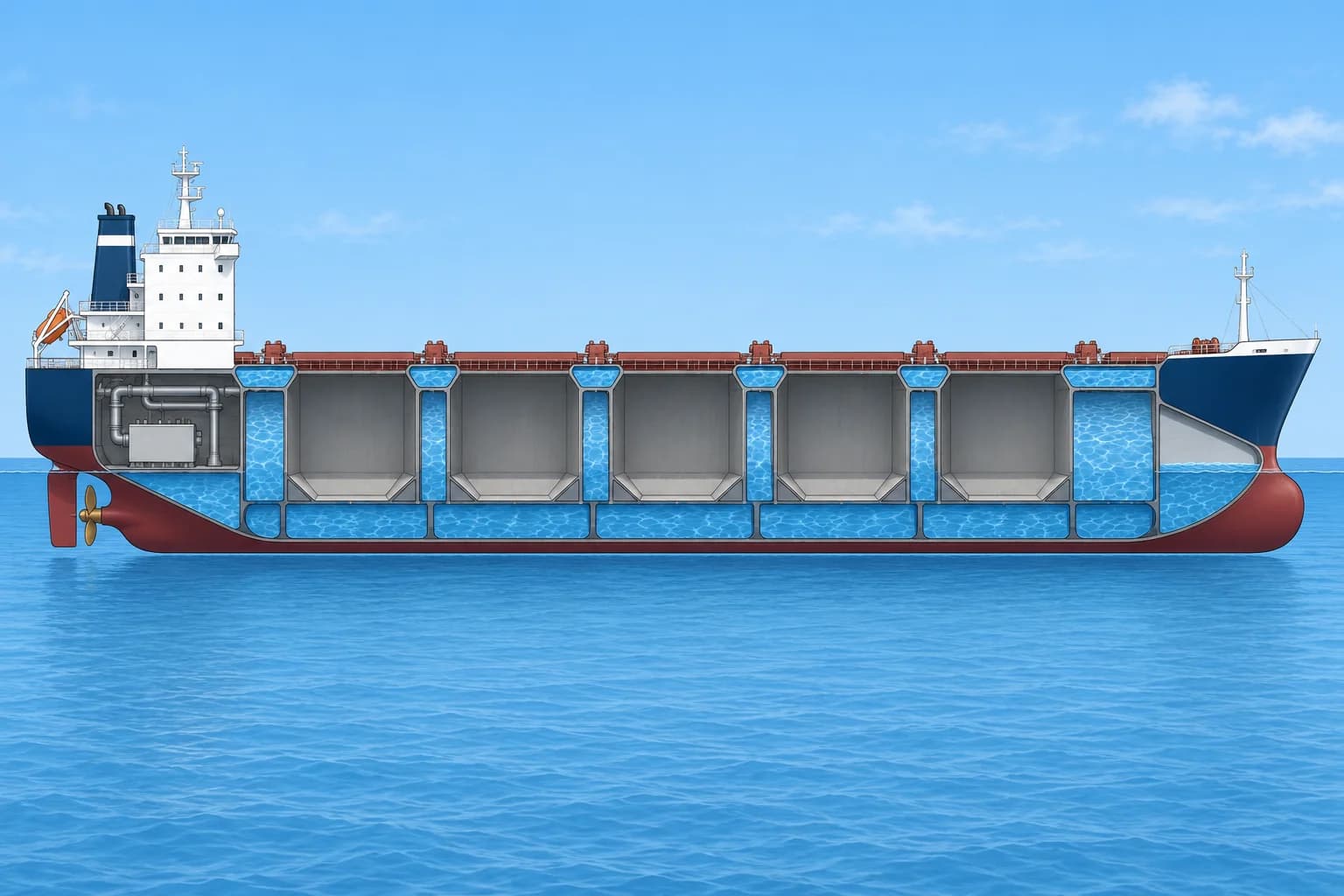
Ballast water in double-bottom, wing, peak and topside tanks gives a light ship enough draught to immerse the propeller and rudder, a safe trim, a clear view ahead and adequate stability. Ballast below the ship’s existing centre of gravity lowers KG; ballast above it raises KG. Some bulk carriers have a ballast hold for heavy weather. Every operation follows the ship’s ballast plan.
Free surface while ballasting
A tank that is filling or emptying is slack: it has a free surface that reduces effective GM (Trim, list and free surface gives the calculation). Work as few slack tanks at once as you can, and port and starboard pairs together so the ship stays upright. Check GM at the worst moment of the operation, not only at the start and finish. Wide slack tanks can cause large free-surface losses; use the booklet’s values.
Strength while ballasting
Ballast changes the shear forces and bending moments along the hull as much as cargo does. During cargo work, ballast must keep pace with the loading or discharge rate. Pump only in the planned order and at the planned rate, and keep the loading instrument updated with actual soundings, the measured depths of liquid in tanks.
The BWM Convention
Ballast carries organisms between ports. The IMO Ballast Water Management (BWM) Convention requires an approved plan and record book; international certification normally applies from 400 GT. D-2 sets discharge limits, normally met using an approved treatment system. Its final phase-in deadline was 8 September 2024; Convention exceptions, exemptions and approved alternatives still apply. D-1 exchange is now mainly a contingency, subject to port-State acceptance. Organism sizes use micrometres (µm); microbe limits use cfu, colony-forming units.
Exchange and stability
D-1 requires at least 95% volumetric exchange; pumping through three tank volumes is accepted. Under B-4, exchange ≥200 nautical miles (nm) from nearest land in water ≥200 m deep; otherwise, as far away as possible, ≥50 nm and ≥200 m, or in a designated area. You need not deviate or delay your voyage. Sequential exchange empties and refills tanks: check stability, draught, trim and strength throughout. Follow the approved sequence. Omit unsafe exchange; record why and notify authorities. Flow-through keeps tanks full but risks overpressure.
Key figures
- D-2: viable organisms
- ≥50 µm: <10/m³; 10–<50 µm: <10/mL (viable)
- D-2: toxigenic V. cholerae O1/O139
- <1 cfu/100 mL or <1 cfu/g wet zooplankton
- D-2: indicator microbes
- E. coli < 250 cfu/100 mL; enterococci < 100 cfu/100 mL
- D-1 exchange
- 95 % by volume, or 3 × tank volume pumped through
- Where to exchange (B-4)
- ≥200 nm/≥200 m; otherwise ≥50 nm/≥200 m, or designated area
- Final D-2 phase-in deadline
- 8 September 2024; applicable exceptions and exemptions remain
Remember
- Ballast gives draught, trim, propeller immersion, a clear view ahead and stability to a light ship.
- Every slack tank cuts effective GM: work few tanks at once, in port and starboard pairs.
- Ballast changes shear forces and bending moments; keep pace with cargo and follow the plan.
- BWM: approved plan and record book; D-2 discharge limits normally met by treatment. D-1 contingencies need port-State acceptance.
- Exchange: normally ≥200 nm/≥200 m; fallback ≥50 nm/≥200 m or designated area. Every stage must be safe; omit unsafe exchange.
Common mistakes
Wrong: Open all the double-bottom tanks at once to finish deballasting faster.
Right: Many slack tanks together add their free surface moments. Work a few tanks at a time, in pairs, and check GM at the worst stage.
Wrong: The treatment system has failed, so we exchange the ballast tank by tank on the way.
Right: Report the failure and agree an accepted contingency before discharge. Exchange needs port-State acceptance and safe conditions at every stage; it is not automatic permission to discharge.
Wrong: Ballast is only water; the stress calculation is about cargo.
Right: Ballast is weight like cargo. A wrong ballast sequence can overstress the hull as easily as a wrong loading sequence.
Worked case
During cargo loading, deballasting falls behind the planned rate. The terminal wants to continue. Actual tank soundings differ from the loading instrument. What do you do?
Show the answer
Tell the chief mate and arrange to slow or stop loading. Update the instrument with actual soundings and check the present and next stages. Resume only at a rate and sequence that keep draught, stability and hull stresses within limits.
Practice question
Why should you avoid having many ballast tanks slack at the same time?
- Their free surface moments add up and reduce GM
- Their weight raises the ship’s KM very quickly
- Their air pipes cannot vent all the tanks at once
- Their soundings stop matching the tank tables
Show the answer
Answer: A. Each slack tank adds a free surface moment. Together they can cut effective GM sharply.
4 · Loading computer
The loading instrument: approved software, honest inputs
The loading instrument calculates draughts, stability and stresses in seconds. It is only as good as its approval, its test conditions and the figures you type in.
What it is
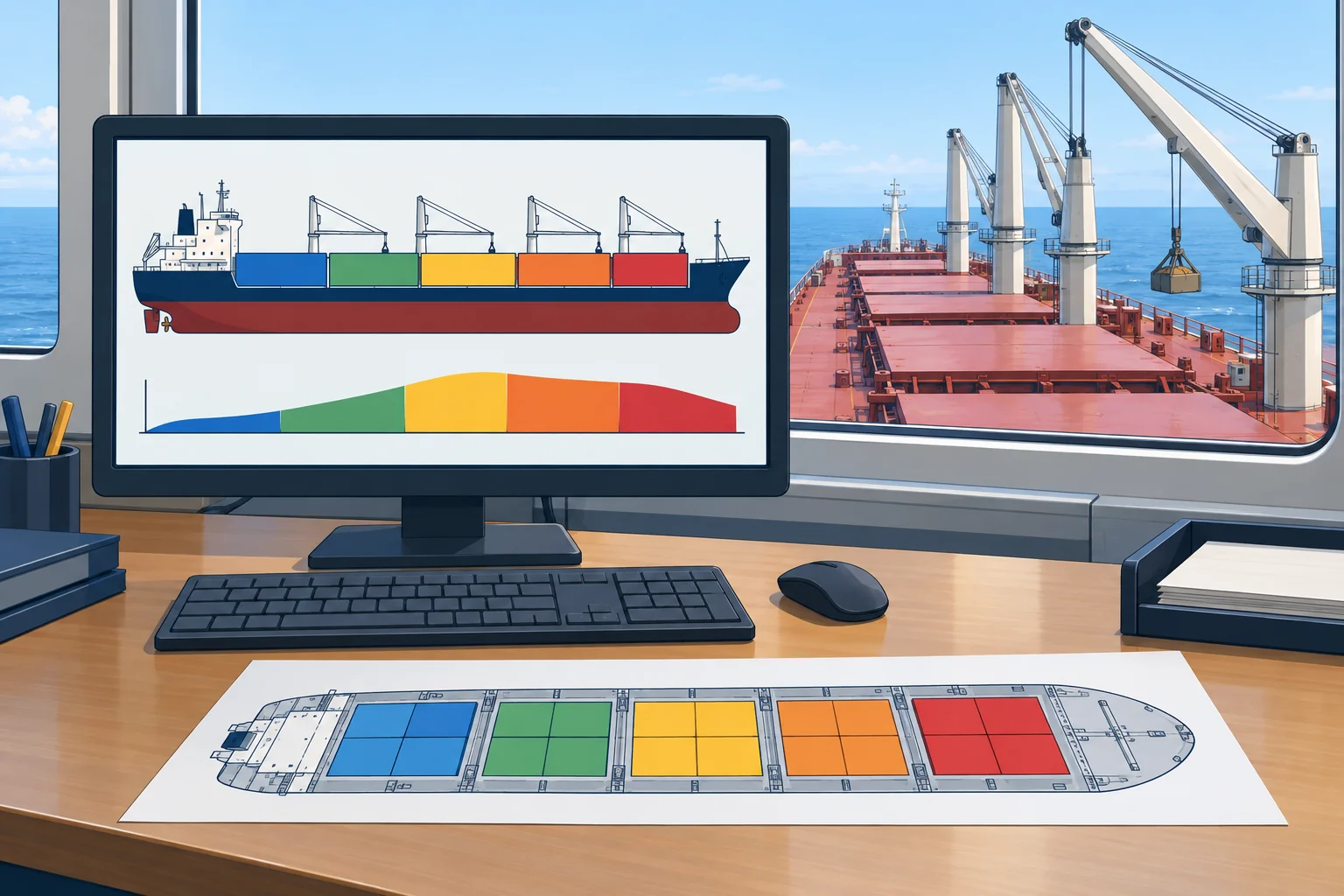
A loading instrument is approved software, with its computer, that calculates draughts, trim, stability and, where fitted, hull shear forces and bending moments for a loading condition. It does not replace the approved stability booklet and loading manual: it uses approved ship data and must reproduce approved test results within accepted tolerances. The ship’s classification society approves it for that ship. Keep the approval and the user manual on board.
Four types
IACS UR L5, a stability-software requirement from the International Association of Classification Societies, defines four types. Type 1 calculates intact stability only. Type 2 calculates intact stability and checks damage stability against a limit curve, a required minimum GM or maximum KG. Type 3 calculates intact stability and damage stability with pre-programmed damage cases. Type 4 calculates damage stability for an actual flooding case, to support safe return to port.
Test conditions
Approval includes test conditions, loading conditions with known results. Run them after software or hardware changes. The master must verify at least one approved condition at each annual survey and retain results for class verification. At special survey, run all approved conditions in the surveyor’s presence. Results must meet approved tolerances. If they fail, stop using it and report the fault. Use an approved alternative covering all required stability and strength checks. If the instrument is mandatory, obtain flag/class acceptance before sailing without it. Demonstrate compliance before sailing; arrange repair.
Garbage in, garbage out
Check every input: lightship and constant; tank soundings and densities; free surface applied to slack tanks as the booklet says (actual or maximum); cargo weights and positions per hold. Use each field’s stated units. When converting volume to tonnes, use the actual liquid density in t/m³. One wrong digit can turn a failing condition into a passing one.
The draught check
Compare calculated draughts with corrected observations. First check readings, trim, hull deflection, water density and matching draught references. Once other causes are excluded, a small mean-draught difference may indicate unaccounted weight. TPC means tonnes per centimetre of immersion: difference in cm × TPC estimates extra tonnes. Calculated 8.62 m, observed 8.70 m: 8 cm × 25 t/cm suggests about 200 t extra. Reconcile the figures before sailing.
Key figures
- Type 1
- Intact stability only
- Type 2
- Intact, plus damage stability checked by a limit curve
- Type 3
- Intact, plus pre-programmed damage cases calculated
- Type 4
- Damage stability for an actual flooding case (return to port)
- Draught check
- Small draught difference (cm) × TPC ≈ unexplained weight (t)
Remember
- The instrument uses approved ship data and agrees within approved tolerances; it does not replace the booklet.
- UR L5 Types: 1 intact; 2 + limit curve; 3 + pre-programmed damage; 4 actual flooding case.
- Failed test: stop using it, report the fault; use an approved alternative covering all required checks or delay departure.
- Check inputs: lightship, constant, soundings, densities, free surface, units.
- Reconcile readings, density, trim, deflection and draught references first; remaining cm × TPC estimates unexplained tonnes.
Common mistakes
Wrong: The computer says the condition passes, so the ship is safe.
Right: It passes only if the inputs are right. Check soundings, densities, weights and free surface, and compare calculated with observed draughts.
Wrong: After a software update the instrument is still approved, so carry on.
Right: Run the approved test conditions after any change. If the results do not match, do not use it until it is corrected.
Worked case
After loading, mean draught is 8.62 m calculated and 8.70 m observed. Readings, trim, hull deflection, water density and draught references have been checked and reconciled. TPC is 25 t/cm. The stability result passes with a small margin. What do you do?
Show the answer
Report it. The remaining 8 cm difference suggests about 8 × 25 = 200 t of unaccounted weight. Recheck tank soundings, cargo figures and the constant. If the weight is high up, real GM may be lower than computed and the small margin may be gone. Do not sail until the difference is explained and the condition recalculated.
Practice question
Which IACS UR L5 type checks damage stability against a limit curve of required GM or maximum KG?
- Type 1
- Type 2
- Type 3
- Type 4
Show the answer
Answer: B. Type 2 calculates intact stability and checks damage stability with a limit curve. Type 3 calculates pre-programmed damage cases directly.
5 · Departure
Before departure: stability, strength and the worst condition
Before you sail, check the actual condition, not the plan, and the worst point of the voyage: stability, strength, draught, view ahead and records.
The departure condition
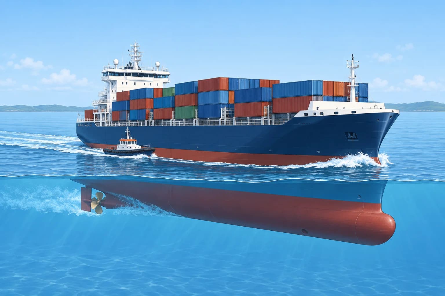
Calculate the final condition from actual figures. Check draughts against voyage load-line limits; GM, corrected for free surface, against the booklet’s minimum; and stability against the approved limiting KG/GM curve or applicable GZ (righting-lever) criteria of the International Code on Intact Stability (IS Code). Check shear forces and bending moments using the limits approved for sea passage.
The worst condition
Stability changes on passage. Fuel is burnt and fresh water used, often from low tanks, so KG usually rises and more tanks go slack. Timber deck cargo can absorb water and ice can build up on deck and superstructure: weight added high. Calculate the arrival condition and any worse point in between. The ship must meet the criteria throughout the voyage, not only when she sails.
Other checks
Check propeller and rudder immersion and suitable trim. From the conning position, SOLAS V/22 requires the sea surface visible within two ship lengths or 500 m forward of the bow, whichever is less, within 10° either side. Check air draught under bridges and under-keel clearance allowing for squat, the sinkage and change of trim caused by moving through water. Secure cargo; set required hatches and watertight and weathertight closures for sea. Keep essential ventilation and tank vents working.
Records
Keep the signed departure stability and strength printout. Record draughts forward, aft and amidships, freeboard and water density in the log book as your flag requires. Port State Control inspects these records, and after an accident they are the first thing investigators ask for.
If it fails
Fix it before you sail. For deficient stability, lower high weights or reduce free surface; removing low weights can worsen GM. Adding low ballast may help, but check its free surface, load line and hull stresses. For overload, reduce weight. Recheck stability, draught, trim and strength at every affected stage. The master authorises sailing only after the revised plan passes; give honest figures.
Departure checklist
- Enter actual cargo, tank soundings and densities. Compare calculated draughts with observed draughts and resolve any unexplained difference. — The plan is not the ship; the check must use what is really aboard.
- Check draughts against the load line for the zone and every zone on the voyage. — The ship must not be overloaded at any point of the passage.
- Check corrected GM and the approved stability limits at departure, arrival and the worst intermediate stage. — Consumption and slack tanks usually make the arrival condition worse.
- Check shear forces and bending moments against the seagoing limits at those stages. — Use the approved seagoing limits, which account for wave loads.
- Check trim, propeller immersion, view ahead, air draught and under-keel clearance allowing for squat. — A ship can pass stability and still be unsafe to navigate.
- Sign and retain the calculation; log draughts, freeboard and density as your flag and company require. — These records let the master and inspectors verify the departure checks.
Remember
- Check actual figures: load line, free-surface-corrected GM, approved stability limits, shear forces and bending moments.
- The arrival or a mid-voyage point is often worse than departure: calculate it.
- Burnt fuel from low tanks, slack tanks, wet timber and ice all raise effective KG.
- SOLAS V/22: sea obscuration ≤2 ship lengths or 500 m forward of the bow, whichever is less, within ±10° ahead.
- Sign and keep the printout; log draughts, freeboard and density.
Common mistakes
Wrong: The departure condition passes, so the voyage is covered.
Right: Calculate arrival and any worse point. Burnt fuel, slack tanks, water absorption and ice can take a passing ship below the criteria.
Wrong: Harbour stress limits are fine for the sea passage.
Right: At sea, use the loading manual’s approved seagoing limits; do not substitute harbour limits.
Worked case
Your departure condition meets every criterion. The arrival condition, after 9 days of fuel burnt from double-bottom tanks and three tanks slack, falls just below the required GM. The ship is ready to sail and the pilot is aboard. What do you do?
Show the answer
Tell the master: the ship does not meet the criteria throughout the voyage, so as calculated she must not sail. Fixes include ballasting a low tank on passage, planned and calculated, or taking ballast low now, drawing fuel so fewer tanks are slack, or adjusting cargo. Recalculate the corrected plan for every stage, record it and then sail.
Practice question
Why is the arrival condition often worse than departure for stability?
- Fuel burnt low down raises KG and leaves tanks slack
- Cargo settles during the voyage and lowers KM
- Sea water density rises as the voyage goes on
- Hull stresses fall, so the margins get smaller
Show the answer
Answer: A. Using fuel and fresh water from low tanks removes low weight and can leave tanks slack. Both effects reduce effective GM.