
Ship stability and stowage · Level P3 · 5 parts · about 19 min
Stress tables, loading instruments and partial loss of intact buoyancy
5 short parts: Shear & bending · Hog & sag · Stress limits · Lost buoyancy · Bilging. Each part explains the idea, then gives the points to remember, the common mistakes, a worked case and a practice question; the Academy unit adds all 31 check questions.
1 · Shear & bending
Shear force and bending moment along the hull
Weight and buoyancy can differ along a ship. This loads the hull girder, the hull acting as a beam, through shear force and bending moment.
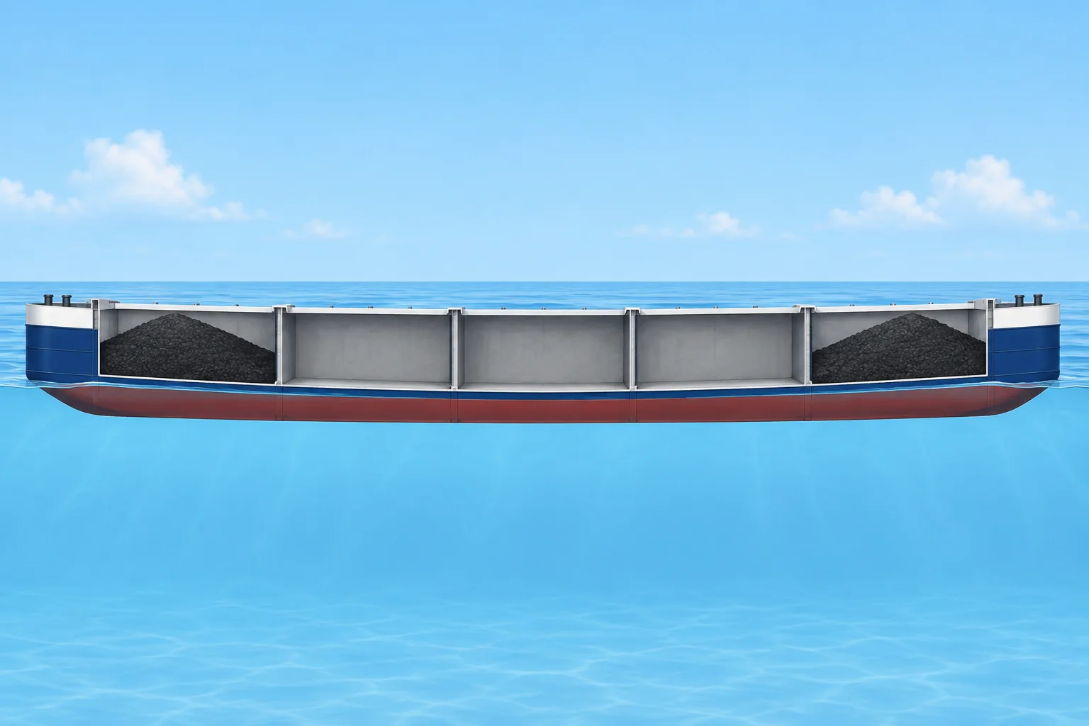
Two distributions
Picture the ship cut into short slices. Each slice has its own weight: steel, cargo, fuel, ballast. Each also gets its own buoyancy from the water it displaces. In total the two balance, so she floats. Slice by slice they rarely match. Where weight exceeds buoyancy the slice wants to sink; where buoyancy wins it wants to rise. The difference per metre is the load curve, in tonnes per metre (t/m).
Shear force
The shear force (SF) at a station is the net load added up from one end of the ship to that station, in tonnes. It tries to slide one part of the hull vertically past the next. SF is zero at both ends. It peaks where the load curve changes sign, often near the quarter lengths or at a heavy hold next to an empty one.
Bending moment
The bending moment (BM) at a station is the shear force added up along the length, in tonne-metres (t·m): the area under the SF curve. BM is zero at both ends and greatest where SF passes through zero, usually near midships. A large BM bends the whole hull like a beam. Don’t confuse it with BM, the metacentric radius of stability.
Computer units
In stress tables, t means tonne-force: the weight force of one tonne. Many loading computers show SF in kilonewtons (kN) and BM in kilonewton-metres (kN·m). Divide by 9.81 to compare: 180,500 kN is about 18,400 t; 1 t·m is about 9.81 kN·m.
Why the officer cares
Excessive SF can buckle or crack side shell and bulkheads near heavy holds. Excessive BM can fracture deck or bottom plating amidships. You control both through the order in which you load, discharge and ballast. The next lessons cover hog and sag, then stress limits and the loading instrument.
Key figures
- Load curve
- Weight − buoyancy per metre, in t/m
- Shear force (SF)
- Net load summed from one end to the station, in t
- Bending moment (BM)
- Area under the SF curve from one end, in t·m
- Maximum BM
- Where SF passes through zero, usually near midships
- At the ends
- SF and BM are both zero
- Units
- 1 t ≈ 9.81 kN; 1 t·m ≈ 9.81 kN·m
Worked example: SF and BM on a box barge
- Set up the barge: 100 m long, five 20 m compartments, lightship 1,000 t spread evenly (10 t/m). Load 600 t in each end compartment. — Displacement is 2,200 t. A level box barge has uniform buoyancy: 2,200 ÷ 100 = 22 t/m.
- Find the load curve. Weight is 10 + 600 ÷ 20 = 40 t/m at the ends and 10 t/m in the middle. Net load = weight − buoyancy. — Ends +18 t/m (too heavy), middle −12 t/m (too buoyant). The net load sums to zero.
- Shear force 20 m from the end: 18 × 20 = 360 t. — SF is the net load summed from the end. It peaks here, where the load changes sign.
- Shear force at midships: 360 − 12 × 30 = 0 t. — SF passes through zero, so BM is at its maximum here.
- Bending moment 20 m from the end: area under the SF triangle = ½ × 20 × 360 = 3,600 t·m. — BM is the area under the SF curve from the end.
- Bending moment at midships: 3,600 + ½ × 30 × 360 = 9,000 t·m. — Add the signed areas under the SF curve from the end to midships.
Remember
- Weight and buoyancy balance in total but not slice by slice; the difference is the load curve.
- SF is the summed load (t); BM is the summed SF (t·m).
- Maximum BM occurs where SF crosses zero; SF peaks where the load curve changes sign.
- Check whether the computer uses t and t·m or kN and kN·m.
Common mistakes
Wrong: If the ship floats at her marks, the hull is not stressed.
Right: Total weight equals total buoyancy, but their spread along the length can still create large SF and BM.
Wrong: Shear force is greatest amidships.
Right: SF usually peaks near the quarter lengths, where the load changes. BM usually peaks near midships, where SF is zero.
Wrong: The BM on the stress screen is the metacentric radius.
Right: Here BM is the bending moment in t·m or kN·m. The metacentric radius BM of stability is a length in metres.
Worked case
A 100 m box barge has lightship 1,000 t spread evenly and 1,200 t of cargo. Compare loading all cargo in the middle 20 m compartment with 240 t in each of five 20 m compartments. Which gives less midships bending?
Show the answer
With cargo concentrated amidships, buoyancy is 22 t/m. Net load is −12 t/m outside the middle and +48 t/m inside. SF reaches −480 t at 40 m and returns to zero amidships. BM = −9,600 − 2,400 = −12,000 t·m. With 240 t per compartment, weight and buoyancy are both 22 t/m throughout: net load, SF and BM are zero. The even distribution gives less midships bending.
Practice question
What is the shear force at a station?
- The net load summed from one end to the station
- The area under the bending moment curve there
- The weight of the cargo directly above that station
- The buoyancy per metre at that station only
Show the answer
Answer: A. SF is the running sum of weight minus buoyancy from one end. BM is the running sum (area) of SF.
2 · Hog & sag
Hogging and sagging: still water, waves and the draught marks
A hull bends even in calm water, and waves add more. Learn to tell hogging from sagging and to measure the bend from the draught marks.
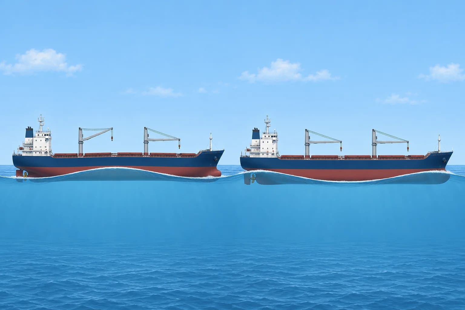
Hogging
In hogging the middle of the ship rises relative to the ends, like an upturned banana. The deck is stretched (tension) and the bottom is squeezed (compression). It happens with heavy ends and light midship holds, or in a wave with its crest amidships and troughs at the ends.
Sagging
In sagging the middle drops relative to the ends. The deck is in compression and the bottom in tension. It happens with heavy midship holds and light ends, or with wave crests at bow and stern and a trough amidships. Compressed plating can buckle, so sagging limits matter for deck plating and hatch coamings, the raised sides around hatch openings.
Still water and waves
The still water bending moment (SWBM) comes from your loading alone. At sea a wave bending moment is added on top, swinging between hog and sag as waves pass. It is largest when the wavelength is close to the ship’s length. The hull is designed for both, so the loading you control must leave room for the wave part.
Reading deflection
Average port and starboard readings at each position. Correct the end readings to the perpendiculars (the ship’s forward and aft reference lines) and the middle reading to true midships before comparing them. Compare the midships mean with the mean of the forward and aft draughts. Midships deeper than the mean of the ends means sagging; shallower means hogging. The difference is the deflection, usually given in centimetres.
Why deflection matters
Hydrostatic tables assume a straight keel. On a sagging ship the mean of the ends understates displacement; on a hogging ship it overstates it. The draught survey’s quarter mean, (F + A + 6M) ÷ 8, corrects for this. A deflection that grows during loading also warns that the plan is bending the hull hard.
Key figures
- Hogging
- Middle up: deck in tension, bottom in compression
- Sagging
- Middle down: deck in compression, bottom in tension
- Deflection
- Midships mean − mean of forward and aft draughts
- Sign
- Positive = sagging; negative = hogging
- Quarter mean
- (F + A + 6 × M) ÷ 8
- Largest wave BM
- Wavelength about equal to the ship’s length
Worked example: deflection from the draught marks
- Use end draughts corrected to the perpendiculars and middle readings at true midships: forward 7.80 m, aft 8.40 m, midships port 8.24 m and starboard 8.26 m, so midships 8.25 m. — Averaging both sides removes the effect of list from the draught reading.
- Mean of forward and aft = (7.80 + 8.40) ÷ 2 = 8.10 m. — This is where midships would float if the keel were straight.
- Deflection = 8.25 − 8.10 = 0.15 m = 15 cm, midships deeper. — Midships deeper than the mean of the ends means sagging.
- Quarter mean = (7.80 + 8.40 + 6 × 8.25) ÷ 8 = 8.2125 m. — This is the conventional quarter-mean approximation for hull deflection.
- With tonnes per centimetre immersion (TPC) = 32 t/cm: (8.2125 − 8.10) × 100 × 32 = 360 t. — Using 8.10 m would understate displacement by about 360 t.
Remember
- Hogging: middle up, deck in tension. Sagging: middle down, deck in compression.
- Still water BM comes from your loading; wave BM is added at sea and alternates.
- Compare the midships draught with the mean of forward and aft to find hog or sag.
- Use the quarter mean, not the mean of the ends, when the keel is bent.
Common mistakes
Wrong: A wave crest amidships causes sagging.
Right: A crest amidships supports the middle and leaves the ends unsupported: hogging. Crests at bow and stern with a trough amidships cause sagging.
Wrong: Deflection is only a problem in heavy weather.
Right: Still water loading alone can bend the hull. Keep the still water BM within limits so there is margin for the wave BM.
Worked case
In port, end draughts corrected to the perpendiculars are forward 6.10 m and aft 7.30 m. At true midships, both sides read 6.62 m. Is the ship hogging or sagging, by how much, and which draught do you use for displacement?
Show the answer
Mean of the ends = (6.10 + 7.30) ÷ 2 = 6.70 m. Midships, at 6.62 m, is 8 cm shallower: hogging 8 cm. Quarter mean = (6.10 + 7.30 + 6 × 6.62) ÷ 8 = 6.64 m. Enter the hydrostatic table with 6.64 m (plus the trim corrections in a draught survey), not 6.70 m.
Practice question
A wave crest is amidships with troughs at bow and stern. What does it cause?
- Sagging, deck in compression
- Hogging, deck in tension
- Sagging, bottom in tension
- Hogging, bottom in tension
Show the answer
Answer: B. The crest supports the middle while the ends lose support, so the hull hogs: deck in tension, bottom in compression.
3 · Stress limits
Stress tables, permissible limits and the loading instrument
Your loading manual and loading instrument show whether shear force and bending moment stay within permissible limits at every station, in port and at sea.
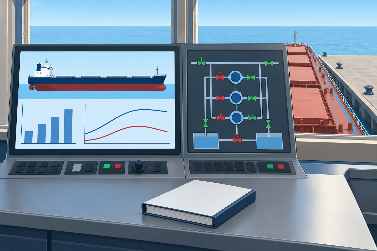
The loading manual
The approved loading manual describes the loading conditions the ship was designed for, the permissible still water SF and BM, and local limits such as tank top loads in t/m². Older or smaller ships may use stress tables: you multiply each weight by a factor for its compartment, add them up, and compare the result with a permitted value.
Stations and limits
Limits are set at reading points, usually at transverse bulkheads and amidships. Use the positive or negative SF limit and the hogging or sagging BM limit that matches the result. Compare magnitudes to find the percentage of the limit used. Many ships have higher harbour limits for calm water in port and lower seagoing limits, because waves add to the still water values at sea.
The loading instrument
A loading instrument is an approved computer program that calculates SF and BM at the reading points, and usually stability too. IACS UR S1 generally requires a loading manual from 65 m and a loading instrument for Category I ships from 100 m; check your ship’s applicable class requirements. SOLAS XII/11 requires one on bulk carriers of 150 m and over. Stability software is approved under IACS UR L5.
Trust but check
Enter every tank, hold and constant correctly: one missing ballast tank changes everything. Run the approved test conditions from its manual and compare the results; class checks this at annual surveys. Watch the units: many programs show kN and kN·m. A green final condition is not enough; check every intermediate stage of the sequence.
Over the limit
If any station exceeds 100 % of its limit, change the plan before you continue: alter the sequence, the pour sizes or the ballast. Never sail with seagoing limits exceeded just because the harbour limits were met. Record the final values in the cargo or stability records.
Key figures
- Result
- % of permissible SF and BM at each reading point
- Example
- 18,400 t ÷ 23,000 t limit = 80 %
- Harbour vs sea
- Harbour limits higher; seagoing limits apply on departure
- IACS UR S1
- Generally: manual ≥65 m; instrument for Category I ≥100 m.
- SOLAS XII/11
- Loading instrument on bulk carriers ≥ 150 m
- IACS UR L5
- Approval of onboard stability software
Checking stresses before and during loading
- Run the program’s approved test condition and compare it with the manual. — Shows the program and hull data still match the approved values.
- Enter and verify the actual planned departure condition: every hold, tank and constant. — Missing items are the commonest cause of a wrong result.
- Check SF and BM percentages at every reading point against the seagoing limits. — The departure condition must be fit for sea, not just for the berth.
- Check each intermediate cargo and ballast stage against approved harbour limits where applicable; otherwise use seagoing limits. — Peak stresses often occur part-way through, not at the end.
- If any value exceeds 100 %, re-plan the sequence, pour sizes or ballast. — Changing the plan is cheaper than cracked plating.
- During loading, compare actual draughts and quantities with the plan and re-run. — Shore figures and ballast rates drift from the plan.
Remember
- At each reading point, use the matching signed SF limit and hogging or sagging BM limit.
- Check every intermediate stage, not only the final condition.
- Departure must meet seagoing limits; harbour limits apply only in port.
- Verify the loading instrument with its approved test conditions.
Common mistakes
Wrong: If the final condition is within limits, the sequence is safe.
Right: Peaks often occur part-way through loading or discharge. Check every stage of the sequence.
Wrong: Within harbour limits means fit to sail.
Right: Harbour limits allow for calm water only. Before departure every station must be within the lower seagoing limits.
Wrong: The loading instrument cannot be wrong.
Right: It is only as good as its inputs and data. Check tank entries, units and the approved test conditions.
Worked case
At the final stage the loading computer shows a BM of 2,185,000 t·m at frame 120. The seagoing limit there is 1,900,000 t·m and the harbour limit 2,470,000 t·m. Departure is in two hours. What do you do?
Show the answer
Frame 120 uses 115 % of its seagoing limit and 88.5 % of its harbour limit. This station passes the harbour BM check only. Do not depart. Re-plan cargo or ballast; check SF and BM at every station and correction stage against approved harbour limits where applicable, otherwise seagoing limits. Continue only if all applicable limits are met throughout. Verify actual inputs and record the revised departure condition, meeting every seagoing limit, before sailing.
Practice question
SF at a bulkhead is 15,600 t and the seagoing limit there is 20,000 t. What percentage of the limit is used?
- 128 %
- 78 %
- 22 %
- 88 %
Show the answer
Answer: B. 15,600 ÷ 20,000 × 100 = 78 %. 128 % divides the wrong way; 22 % is the margin left.
4 · Lost buoyancy
Partial loss of intact buoyancy: two ways to calculate
When a compartment floods, you can treat it as lost buoyancy or as added weight. Both give the same Δ × GM, with different numbers on the way.
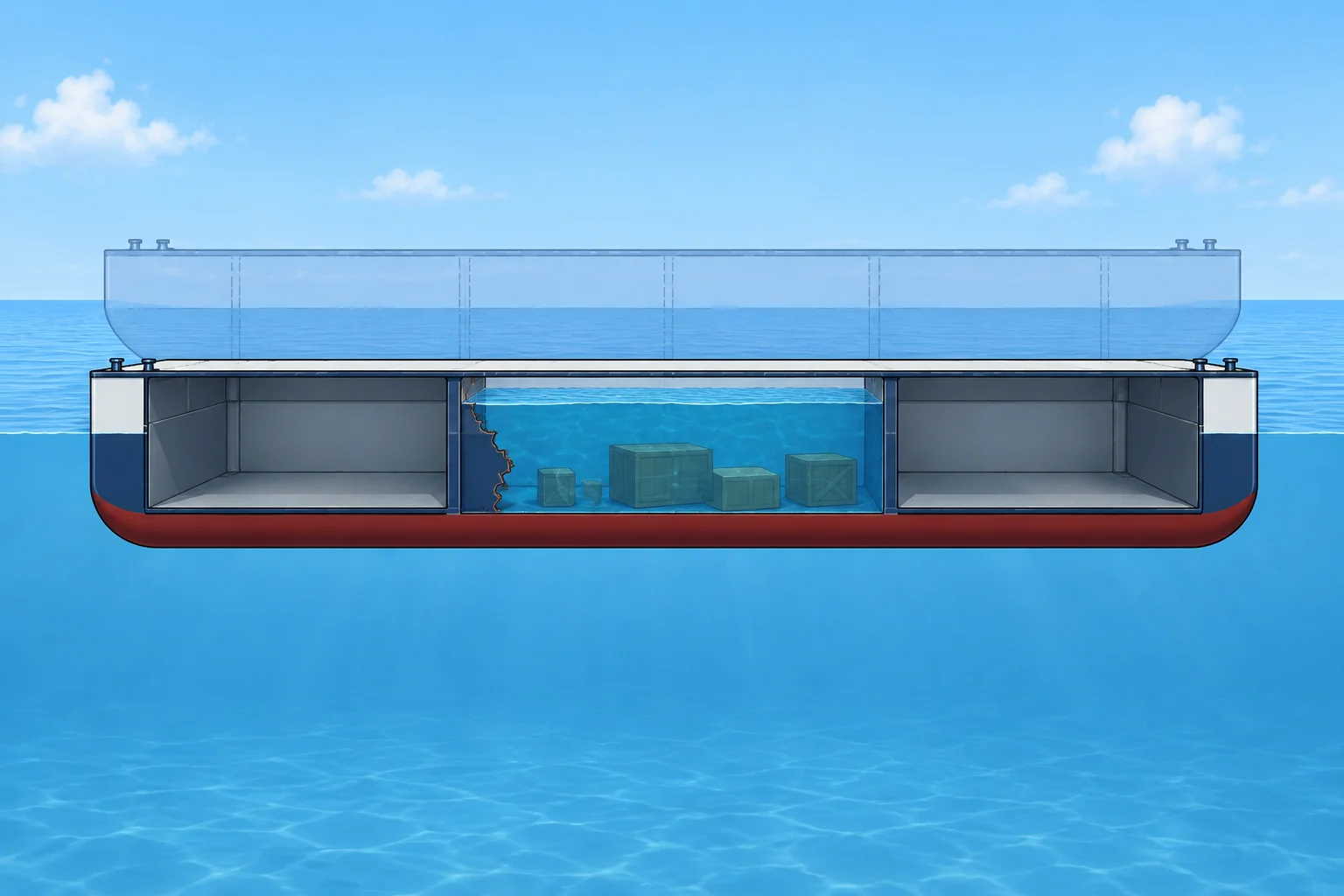
What happens
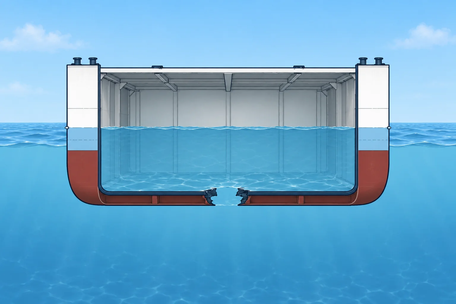
Open a compartment to the sea below the waterline and water fills it to the outside level. The ship loses the buoyancy that space gave. She sinks until the remaining intact volume replaces it. She also trims or lists if the space is off-centre or away from the centre of flotation, the point she trims about. Flooding a compartment like this is called bilging.
Permeability
Permeability, μ (mu), is the fraction of a space’s volume water can fill. SOLAS II-1/7-3 uses 0.60 for stores, 0.95 for accommodation and voids, and 0.85 for machinery. Dry cargo and container spaces take 0.70, 0.80 or 0.95, from the deepest to the lightest draught. An empty geometric volume approaches 1; statutory void-space calculations use 0.95. For liquid spaces, use 0 or 0.95, whichever is more severe.
Lost buoyancy method
Also called the constant displacement method. The flooded space no longer counts as part of the ship. Displacement and KG stay the same. Recalculate the intact hull’s buoyancy geometry and hydrostatic values. For a wall-sided box sinking upright without trim, sinkage = original lost volume ÷ intact waterplane area. The recalculated geometry already accounts for flooding. Do not add a second free-surface correction for flood water: it is part of the sea. Retain free-surface corrections for other slack tanks.
Added weight method
The flood water is treated as weight added to the ship. Displacement rises, KG moves towards the water’s centre, and the flood water’s free surface counts. Hydrostatics come from the tables at the new displacement. It suits spaces that are only partly flooded and is how many flooding computers work. It takes several steps, because the water level inside depends on the new draught.
Same answer, different GM
Both methods give the same final draught and initial righting stiffness, Δ × GM. At small heel angle θ, righting moment ≈ Δ × GM × sin θ. With positive GM, added weight gives a smaller GM because Δ is larger. Keep each method’s Δ, KG, KM and free-surface treatment together. For practical leak control, see Emergencies: flooding.
Key figures
- Permeability μ
- Fraction of a space’s volume that flood water can fill
- SOLAS II-1/7-3
- Stores 0.60; machinery 0.85; accommodation and voids 0.95
- Cargo spaces (7-3)
- Dry cargo 0.70 / 0.80 / 0.95 at deepest / partial / light draught
- Sinkage: wall-sided box
- Original lost volume ÷ intact waterplane area; upright, no trim
- Lost buoyancy method
- Δ and KG constant; no extra flood-water free-surface correction
- Both methods
- Same draught and initial righting stiffness, Δ × GM
Remember
- Bilging: the ship sinks until intact volume replaces the lost buoyancy.
- Permeability is the fraction of a space that water can fill.
- Lost buoyancy: Δ and KG unchanged, geometry recalculated, no extra flood-water free-surface correction.
- Added weight: Δ rises, KG changes and the flood water’s free surface counts.
- Both give the same draught and the same Δ × GM; never mix their figures.
Common mistakes
Wrong: A flooded hold full of cargo loses its whole volume of buoyancy.
Right: Only the permeable part floods. Multiply the volume by its permeability, e.g. 0.70 for dry cargo at the deepest draught.
Wrong: The two methods give different GMs, so one must be wrong.
Right: Different GMs alone do not show an error. Compare final draught and initial righting stiffness, Δ × GM; keep each method’s figures together.
Wrong: Add another free-surface correction for flood water in the lost buoyancy method.
Right: The flood water belongs to the sea. Recalculated geometry accounts for it; another correction for this water counts it twice. Retain corrections for other slack tanks.
Worked case
A box-shaped vessel is bilged amidships. Added weight gives GM 0.992 m at Δ 8,811 t; lost buoyancy gives GM 1.137 m at Δ 7,688 t. Do the different GMs alone show that one calculation is wrong?
Show the answer
No. Initial righting stiffness is Δ × GM: 7,688 × 1.137 ≈ 8,741 t·m and 8,811 × 0.992 ≈ 8,741 t·m. The products are consistent; this alone does not validate either complete calculation. They predict approximately the same heel under the same small heeling moment. Keep each method’s Δ, KG, KM and free-surface treatment together.
Practice question
Equal submerged volumes of a machinery space and a storeroom flood. Using the stated SOLAS values, which loses more buoyancy?
- The storeroom: its permeability is higher
- The machinery space: its permeability is higher
- Both spaces: their submerged volumes are equal
- Neither space: the ship’s weight is unchanged
Show the answer
Answer: B. Lost buoyancy volume equals submerged volume × permeability. Machinery uses 0.85; stores use 0.60.
5 · Bilging
Bilging a midships compartment: a worked example
Work through a bilged midships compartment in a box-shaped vessel: sinkage, new draught, KB, BM and GM, with permeability.
The model
Use an initially upright, untrimmed box-shaped vessel with vertical sides and a flat bottom. Assume freely vented flooding and uniformly spread obstructions, so the same μ applies to volume, waterplane area and waterplane inertia. The compartment runs the full breadth, is centred at the centre of flotation, and extends from the bottom to a watertight deck above the final waterline. Under these assumptions she sinks without list or trim. Real hulls and non-uniform spaces need their own buoyancy geometry.
Sinkage
Lost volume = μ × l × B × d, where L is ship length, l compartment length, B breadth and d initial draught. The intact waterplane = (L − μl) × B. Sinkage = lost volume ÷ intact waterplane = μ × l × d ÷ (L − μl). The waterplane shrinks too: the flooded part no longer provides waterplane area.
New KB and BM
The intact underwater shape is still a box section, so new KB = new draught ÷ 2. Volume of displacement V is unchanged in the lost buoyancy method. The waterplane’s second moment of area, I, measures how its area is spread across the centreline: I = (L − μl) × B³ ÷ 12. New BM = I ÷ V. Then KM = KB + BM and GM = KM − KG, with KG unchanged.
Reading the result
In this example GM falls because BM drops by more than KB rises. In another box vessel, KB’s rise can outweigh BM’s fall, so calculate the result rather than assume its direction. Freeboard falls by the sinkage. Check that the new waterline stays below openings that could let water spread, and that the ship is still within her damage stability limits.
Off-centre and end compartments
A side compartment also causes a list; one away from the centre of flotation also causes trim. Those cases move the centre of flotation and need more steps. The damage stability rules for ships are in the set on damage stability, strength and the draught survey.
Key figures
- Sinkage (box, midships)
- μ × l × d ÷ (L − μl)
- New KB (box)
- New draught ÷ 2
- New BM
- (L − μl) × B³ ÷ 12 ÷ V, with V unchanged
- GM after bilging
- New KM − original KG (lost buoyancy method)
- Worked example
- Sinkage 0.731 m; GM 1.25 m → 1.137 m
Worked example: box vessel bilged amidships
- Intact vessel: L 100 m, B 15 m, d 5.00 m, KG 5.00 m. V = 7,500 m³, Δ = 7,687.5 t. KB 2.50, BM = 15² ÷ (12 × 5) = 3.75, KM 6.25, GM 1.25 m. — This is the baseline to compare with.
- A 15 m compartment amidships floods, μ 0.85. Lost volume = 0.85 × 15 × 15 × 5 = 956.25 m³. Intact waterplane = (100 − 12.75) × 15 = 1,308.75 m². — Only 85 % of the space floods, and that part leaves the waterplane.
- Sinkage = 956.25 ÷ 1,308.75 = 0.731 m. New draught = 5.731 m. — The intact volume must replace the lost buoyancy.
- New KB = 5.731 ÷ 2 = 2.865 m. — The intact underwater shape is still a box section.
- I = 87.25 × 15³ ÷ 12 = 24,539 m⁴. BM = 24,539 ÷ 7,500 = 3.272 m. — V stays 7,500 m³: displacement is unchanged.
- KM = 2.865 + 3.272 = 6.137 m. GM = 6.137 − 5.00 = 1.137 m. — GM falls by 0.113 m and freeboard by 0.731 m.
Remember
- Lost volume = μlBd; intact waterplane = (L − μl)B. Divide these to find sinkage.
- In a box, the new KB is half the new draught; V and KG do not change.
- BM falls because the flooded part no longer adds waterplane inertia.
- A full-breadth compartment centred at the box’s flotation centre causes sinkage only; side/end spaces add list/trim.
Common mistakes
Wrong: Divide the lost volume by the full waterplane area.
Right: The flooded part has no waterplane. Use (L − μl) × B, or you understate sinkage: 0.638 m instead of 0.731 m here.
Wrong: Ignore permeability for a machinery space.
Right: Use 0.85. Taking 1.0 gives 0.882 m of sinkage instead of 0.731 m.
Wrong: Use a new, larger displacement to find BM.
Right: In the lost buoyancy method V and Δ do not change. Use the original 7,500 m³.
Worked case
A box-shaped barge 120 m long and 20 m wide floats at 6.00 m. A full-breadth midships compartment 12 m long, cargo permeability 0.60, is bilged. An unprotected opening to another space is 6.30 m above the keel. Can the one-compartment result describe the final condition?
Show the answer
The model gives lost volume 864 m³ and intact waterplane 2,256 m²: sinkage 0.383 m, draught 6.383 m. This is above the opening at 6.30 m. Water can spread, so the one-compartment calculation cannot establish the final condition.
Practice question
A box vessel 80 m long floats at 4.00 m. A full-breadth midships compartment 10 m long, permeability 0.95, floods. What is the sinkage?
- 0.475 m
- 0.571 m
- 0.539 m
- 0.500 m
Show the answer
Answer: C. 0.95 × 10 × 4 ÷ (80 − 9.5) = 38 ÷ 70.5 = 0.539 m. 0.475 m ignores the lost waterplane; 0.571 m ignores permeability.