
Ship stability and stowage · Level P3 · 5 parts · about 18 min
Trim, list and free surface
5 short parts: Trim basics · Shifting weight · Load & discharge · List and loll · Free surface. Each part explains the idea, then gives the points to remember, the common mistakes, a worked case and a practice question; the Academy unit adds all 31 check questions.
1 · Trim basics
Trim, LCF, LCB and MCTC
Trim is the difference between the aft and forward draughts. The ship trims about the centre of flotation, and MCTC tells you how easily.
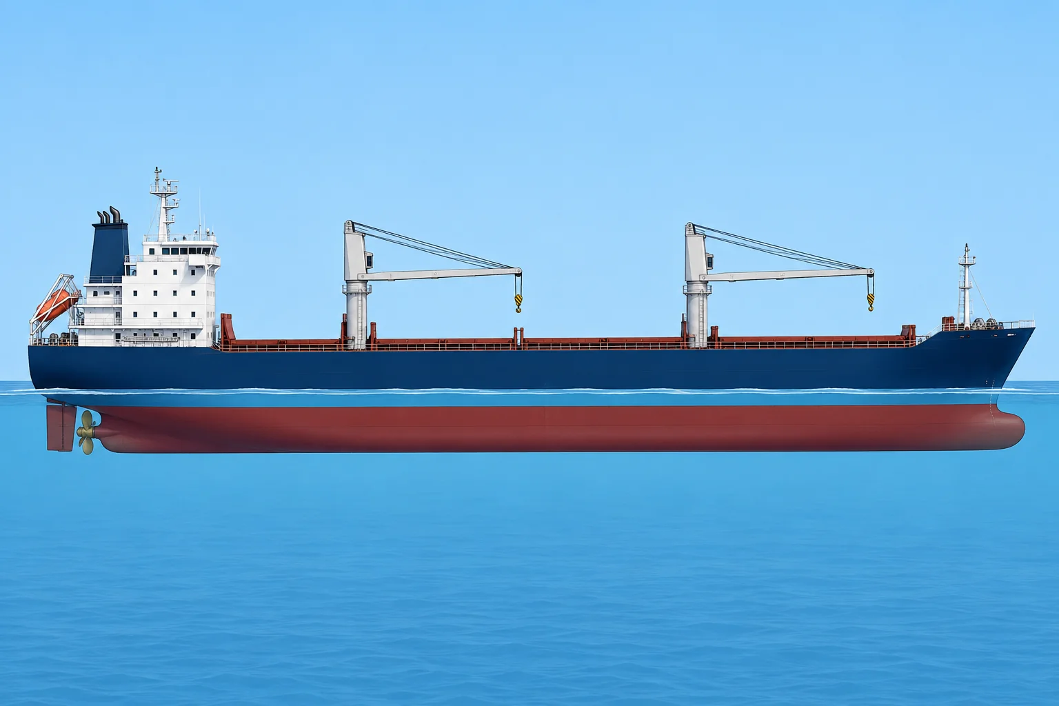
Trim
Trim is the draught aft minus the draught forward, at the perpendiculars. Deeper aft is trim by the stern; deeper forward, trim by the head; equal draughts, even keel. Most ships sail slightly by the stern for steering, propeller immersion and a drier forecastle. The best trim is ship-specific: use the booklet or the owner's trim tables.
Longitudinal centres
Positions along the ship are measured from the aft perpendicular (AP) or from midships: check your booklet's convention. LCG is the longitudinal centre of gravity. LCB is the centre of the underwater volume. LCF, the centre of flotation, is the centre of the waterplane area. The hydrostatic tables give LCB and LCF; you calculate LCG.
She trims about the LCF
For a small change of trim at constant displacement, the ship rotates approximately about the LCF, leaving its draught unchanged. The true mean draught is the draught there. Use it with even-keel hydrostatics only within the approved small-trim limits; otherwise use approved trim-dependent data.
MCTC
The moment to change trim one centimetre, MCTC, is the trimming moment in t·m that changes trim by 1 cm. MCTC ≈ Δ × GML ÷ (100 × LBP), where Δ is displacement in tonnes, GML is longitudinal metacentric height in metres, and LBP is length between perpendiculars in metres. For the same displacement and length, larger GML means larger MCTC and less trim change. Use the condition's tabulated MCTC.
Balance fore and aft
Use LCB from the even-keel hydrostatic table at the condition's displacement. LCG aft of that reference LCB gives trim by the stern; forward gives trim by the head. As the ship trims, buoyancy moves until G and B lie on one vertical.
Key figures
- Trim
- Trim = draught aft − draught forward
- True mean draught
- Draught at the LCF
- Draught at LCF
- dA − trim × (LCF from AP ÷ LBP)
- MCTC
- MCTC ≈ Δ × GML ÷ (100 × LBP), in t·m/cm
- Change of trim
- Trimming moment ÷ MCTC, in cm
Worked example: true mean draught
- Data: LBP 140 m; draughts F 7.577 m, A 8.377 m; LCF 66.0 m forward of the AP. — Draughts already corrected to the perpendiculars.
- Trim = 8.377 − 7.577 = 0.800 m by the stern. — The aft draught is deeper.
- Mean of draughts = (7.577 + 8.377) ÷ 2 = 7.977 m. — This is the draught amidships, not at the LCF.
- LCF lies 70.0 − 66.0 = 4.0 m aft of midships. Correction = 0.80 × 4.0 ÷ 140 = 0.023 m. — The waterline is deeper aft, and the LCF is aft of midships.
- True mean draught ≈ 7.977 + 0.023 = 8.000 m. — Same as 8.377 − 0.800 × 66 ÷ 140, rounded. Use 8.000 m within approved small-trim limits.
Remember
- Trim = aft draught − forward draught; by the stern when deeper aft.
- The ship trims about the LCF, so the draught there is the true mean draught.
- MCTC is the moment that changes trim by 1 cm.
- LCG aft of the even-keel LCB gives stern trim; forward gives head trim.
Common mistakes
Wrong: The mean of the forward and aft draughts is the draught to use in the hydrostatics.
Right: Within approved small-trim limits, use the draught at the LCF. The simple mean is correct only when the LCF is amidships or she is on even keel.
Wrong: The ship trims about midships.
Right: She trims about the LCF, the centre of the waterplane, which moves with draught.
Wrong: MCTC is a fixed number for the ship.
Right: MCTC changes with draught. Read it from the hydrostatics for the condition.
Worked case
A cadet uses the mean, 7.977 m, from F 7.577 m and A 8.377 m. LBP is 140 m; LCF is 74 m forward of AP. They say stern trim always means adding a correction. Do you agree, and what draught should you use?
Show the answer
No. LCF is 4 m forward of midships, where this stern-trimmed waterline is shallower. Use 7.977 − 0.800 × 4 ÷ 140 ≈ 7.954 m. Choose the correction sign from the position of LCF and the direction of trim.
Practice question
Draughts are F 7.577 m and A 8.377 m. What is the trim?
- 0.80 m by the head
- 7.977 m mean trim
- 0.40 m by the stern
- 0.80 m by the stern
Show the answer
Answer: D. Trim = 8.377 − 7.577 = 0.800 m. Deeper aft means trim by the stern.
2 · Shifting weight
Shifting weight fore and aft
A shift fore and aft leaves displacement unchanged and makes a trimming moment. Divide by MCTC, then share the change via the LCF.
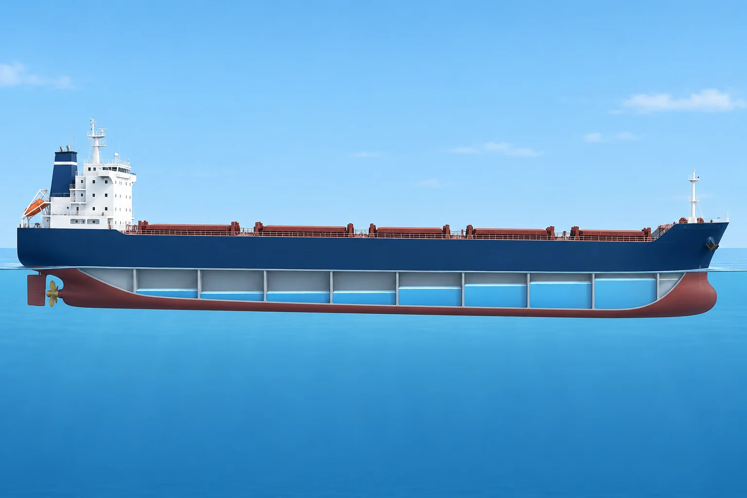
The trimming moment
Moving a weight w a distance d fore and aft makes a trimming moment w × d, in t·m. Displacement does not change, so the ship does not sink. She rotates about the LCF. Change of trim (cm) = w × d ÷ MCTC, towards the end the weight moved to.
Sharing the change
The end farther from the LCF moves more. AP is the aft perpendicular; FP is the forward perpendicular. Change aft = change of trim × distance from AP to LCF ÷ LBP. Change forward = change of trim × distance from LCF to FP ÷ LBP. One end sinks; the other rises. Split the change equally only when the LCF is amidships.
Signs
Write the old draughts. Add the share at the end the weight moved towards; subtract the other share. Then check: new trim = old trim ± change of trim. Sign errors are the commonest mistake in exams and on board, and this check catches them.
Using it
Officers move ballast or fuel fore and aft to reach a required trim: for a draught limit, propeller immersion or an even-keel draught survey. Turn the formula round: w = required change of trim × MCTC ÷ d.
Side effects
MCTC changes with draught, so use the value for the condition. A ballast transfer also leaves slack tanks while it runs, adding free surface.
Key figures
- Change of trim
- COT (cm) = w × d ÷ MCTC
- Change aft
- COT × LCF from AP ÷ LBP
- Change forward
- COT × LCF from FP ÷ LBP
- Weight to shift
- w = required COT × MCTC ÷ d
- Displacement
- Unchanged by a shift: no sinkage
Worked example: moving ballast forward
- Data: Δ 15,000 t, MCTC 180 t·m/cm, LBP 140 m, LCF 66.0 m forward of the AP; F 7.577 m, A 8.377 m. — The condition from Trim basics.
- Move 300 t of ballast 60 m forward: moment = 300 × 60 = 18,000 t·m. — Δ is unchanged, so there is no sinkage.
- Change of trim = 18,000 ÷ 180 = 100 cm by the head. — The weight went forward.
- Aft: 100 × 66 ÷ 140 = 47.1 cm. Forward: 100 × 74 ÷ 140 = 52.9 cm. — The LCF is 74 m from the FP.
- New draughts: F 7.577 + 0.529 = 8.106 m; A 8.377 − 0.471 = 7.906 m. — The forward end sinks and the aft end rises.
- Check: 0.80 m by the stern − 1.00 m = 0.20 m by the head. 8.106 − 7.906 = 0.200 m. — The trim check catches sign errors.
Remember
- A shift fore and aft changes trim, not displacement.
- Change of trim = w × d ÷ MCTC, towards the end the weight moved to.
- Share the change about the LCF: the end farther from it moves more.
- Always check the new trim against old trim ± change of trim.
Common mistakes
Wrong: Split the change of trim half forward and half aft.
Right: Share it in proportion to the LCF's distance from each perpendicular. Halves are right only with the LCF amidships.
Wrong: Add sinkage for a weight moved within the ship.
Right: Δ is unchanged. Only the trim changes.
Wrong: Measure d from midships.
Right: For a shift, d is the distance the weight moves. For a weight loaded, it is measured from the LCF.
Worked case
Trim must fall from 0.80 m to 0.20 m by the stern. Ballast can move 50 m forward; MCTC is 180 t·m/cm. LBP is 140 m and LCF is 66 m forward of AP. The bow can deepen by only 0.25 m. Can this transfer meet both limits?
Show the answer
The trim target needs 60 cm by the head: w = 60 × 180 ÷ 50 = 216 t. The bow deepens by 60 × 74 ÷ 140 = 31.7 cm, exceeding the 25 cm allowance. Do not approve this transfer as planned. Replan for both limits, tank capacity and free surface. Confirm final draughts and trim.
Practice question
200 t is moved 45 m aft. MCTC is 180 t·m/cm. What is the change of trim?
- 50 cm by the head
- 5 cm by the stern
- 50 cm by the stern
- 500 cm by the stern
Show the answer
Answer: C. 200 × 45 ÷ 180 = 50 cm, towards the end the weight moved to: by the stern.
3 · Load & discharge
Loading and discharging: sinkage, trim and final draughts
Loading a weight sinks the ship and trims her about the LCF. Work the two effects separately, then add them at each end.
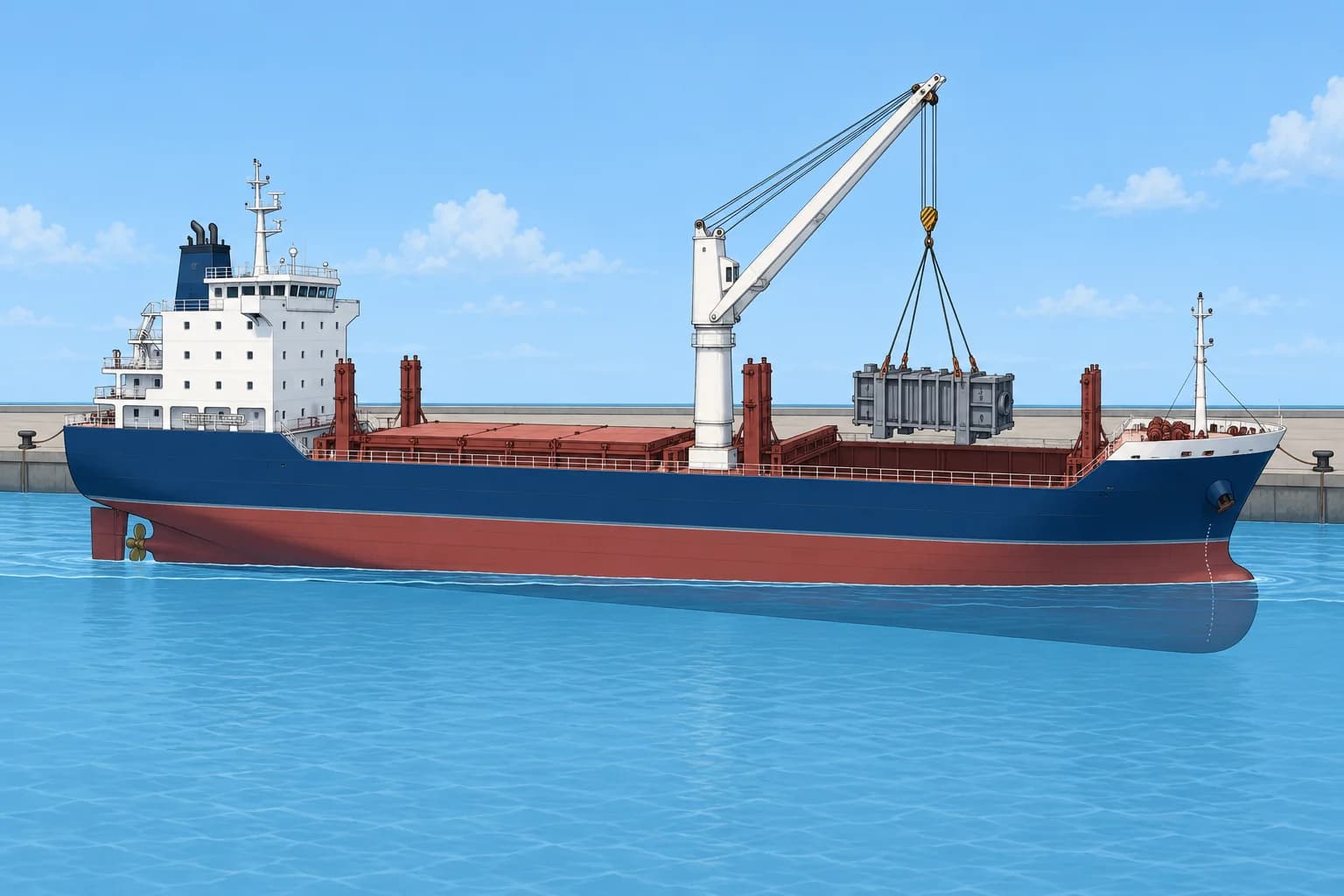
Two effects
Imagine loading first at the LCF. Both ends sink by w ÷ TPC cm. TPC means tonnes per centimetre immersion. Then move it to its real position: the trimming moment is w × d, with d measured from the LCF. Discharging works the same way with w taken off: she rises, and trims away from the end where the weight came off.
When it is accurate
This method suits weights that are small compared with Δ. TPC, MCTC and LCF all change with draught. For a larger change, take them at the mean of the old and new draughts, or use the LCG method below.
The LCG method
Sum weights and longitudinal moments for Δ and LCG. Read LCB, LCF, MCTC and draught at LCF (dLCF) from even-keel hydrostatics at Δ. With positions forward from AP, H (cm) = Δ × (LCG − LCB) ÷ MCTC is head-positive; H < 0 means stern trim. Draughts in metres: dA = dLCF − (H/100) × AP–LCF/LBP; dF = dLCF + (H/100) × LCF–FP/LBP, where FP is the forward perpendicular. This small-trim estimate needs approved trim-dependent data for larger trim.
Several weights
Use a table: weight, distance from the LCF (forward +, aft −) and moment. Sum the weights for sinkage and the moments for trim. The loading computer does this, but you must be able to check it and spot an input error, such as cargo entered in the wrong hold.
The limits
Final draughts must respect the load line, the berth and channel depth with under-keel clearance, air draught, and any trim the master requires. Check the arrival condition too: fuel and water used on passage change both draught and trim.
Key figures
- Sinkage
- Sinkage (cm) = w ÷ TPC
- Change of trim
- COT (cm) = w × d from LCF ÷ MCTC
- Head-positive trim
- H (cm) = Δ × (LCG − LCB) ÷ MCTC; even-keel LCB
- Draught aft
- dA (m) = dLCF − (H ÷ 100) × (AP to LCF) ÷ LBP
- Draught forward
- dF (m) = dLCF + (H ÷ 100) × (LCF to FP) ÷ LBP
Worked example: loading forward of the LCF
- Data: Δ 15,000 t, TPC 25 t/cm, MCTC 180 t·m/cm, LBP 140 m, LCF 66 m forward of AP; F 7.577 m, A 8.377 m. — Initial draughts are rounded from dLCF 8.000 m. Keep unrounded values.
- Load 400 t, 30 m forward of the LCF. Sinkage = 400 ÷ 25 = 16 cm. — Bodily sinkage, the same at both ends.
- Change of trim = 400 × 30 ÷ 180 = 66.7 cm by the head. — d is measured from the LCF.
- Forward: +16 + (200/3) × 74 ÷ 140 ≈ +51.24 cm. Aft: +16 − (200/3) × 66 ÷ 140 ≈ −15.43 cm. — Add sinkage and trim share at each end, keeping change of trim = 200/3 cm unrounded.
- Final (using unrounded values): F ≈ 8.090 m; A ≈ 8.223 m. — Trim is now about 0.133 m by the stern: 0.800 − 0.667. Carry unrounded draughts and changes through the calculation.
Remember
- Loading = sinkage (w ÷ TPC) plus trim (w × d from the LCF ÷ MCTC).
- Measure d from the LCF, not from midships.
- H (cm) = Δ × (LCG − even-keel LCB) ÷ MCTC: head-positive; divide H by 100 for draughts in metres.
- Check final draughts against the load line, depth, air draught and arrival condition.
Common mistakes
Wrong: Measure the loading distance from midships.
Right: The ship trims about the LCF, so measure d from the LCF.
Wrong: Use the old TPC and MCTC for a very large load.
Right: Use values at the mean draught, or work the final condition with the LCG method.
Wrong: Discharging forward trims her by the head.
Right: Removing weight forward lifts the bow: she trims by the stern.
Worked case
At Δ 15,000 t, LCG is 69.54 m and even-keel table LCB is 70.50 m forward of AP. MCTC is 180 t·m/cm; draught at LCF is 8.000 m. LCF is 66 m forward of AP; LBP is 140 m. The berth allows 8.30 m aft after required under-keel clearance. Can you accept?
Show the answer
H = 15,000 × (69.54 − 70.50) ÷ 180 = −80 cm: stern trim. H/100 = −0.80 m. Aft: 8.000 − (−0.80) × 66 ÷ 140 ≈ 8.377 m. Forward: 8.000 + (−0.80) × 74 ÷ 140 ≈ 7.577 m. Reject: aft draught exceeds 8.30 m by about 0.077 m. Revise the loading or trim and recalculate both draughts.
Practice question
You load 250 t at the LCF. TPC is 25 t/cm. What happens?
- She trims 10 cm by the head
- She sinks 10 cm at both ends
- She sinks 1 cm at both ends
- She sinks 10 cm aft only
Show the answer
Answer: B. A load at the LCF causes bodily sinkage only: 250 ÷ 25 = 10 cm.
4 · List and loll
List: finding it, correcting it, and telling it from loll
A list comes from G off the centreline with positive GM. Loll comes from negative GM. They look alike and need different fixes.
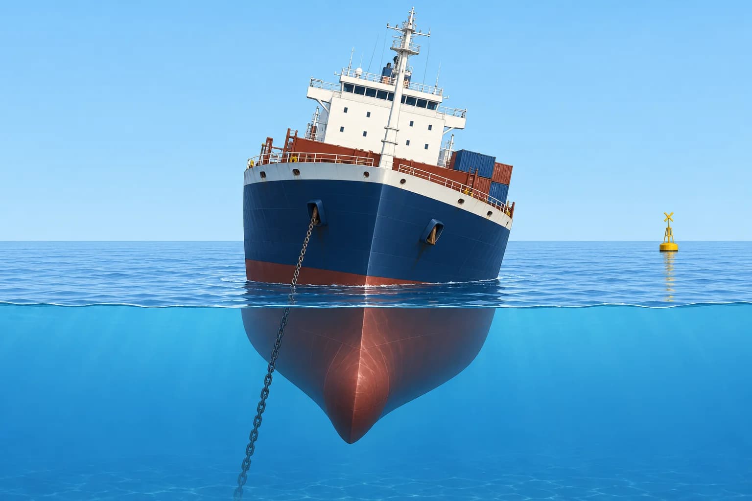
Finding the list
With positive GM, G off the centreline by GGH gives a list: tan θ = GGH ÷ GM, using GM fluid. Get GGH from a table of transverse moments: GGH = Σ(w × y) ÷ Δ, with y each weight's distance off the centreline and sides given opposite signs. Use this formula only for small lists.
Correcting it
To bring her upright, create an equal and opposite moment, Δ × GGH. Transfer ballast or fuel across, or load the next cargo on the high side. Moving w across a distance y gives w × y. Plan with full and empty tanks in mind: a slack wing tank adds free surface while you work.
Loll
With negative GM fluid, the ship is unstable upright. She may capsize or settle at an angle of loll, a heeled equilibrium where GZ returns to zero. Signs: she lies over with no off-centre weight to explain it, rolls slowly about the leaning angle, and may flop to the other side. Slack tanks, fuel used from low tanks, water on deck or ice can cause it at sea.
Correcting loll safely
Confirm the loading condition and negative GM fluid. Follow the approved recovery plan to lower G. A usual sequence is to fill a low, divided double-bottom tank on the low side first, then its partner, one at a time. Lower or remove high weights where practicable. Do not transfer ballast across to the high side to counter the heel: she can flop farther the other way. Monitor intermediate GM fluid and heel; the first tank can initially increase the heel.
List or loll?
Both can involve rolling about a heeled equilibrium. Slow rolling or changing sides suggests loll but does not prove it. Check weight positions, tank levels and calculated GM fluid. Positive GM with G off the centreline indicates list; negative GM indicates loll. If uncertain, stop sideways transfers and check the loading condition before pumping. Correct a list by transverse transfer only after confirming positive GM fluid.
Key figures
- List angle
- tan θ = GGH ÷ GM fluid (small angles)
- Shift of G across
- GGH = Σ(w × y) ÷ Δ
- Correcting moment
- Δ × GGH, applied to the high side
- Loll
- Negative GM: lower G, low-side divided tank first
- Never with loll
- Do not transfer weight to the high side
Worked example: correcting a list with ballast
- Data: Δ 15,000 t, GM fluid 0.55 m. After loading, G lies 0.08 m to port. — GM is positive, so this is a list, not loll.
- List: tan θ = 0.08 ÷ 0.55 = 0.145, θ ≈ 8.3° to port. — Small enough for the small-angle formula.
- Moment to remove = 15,000 × 0.08 = 1,200 t·m. — An equal moment to starboard brings G back to the centreline.
- Wing tanks lie 8 m each side of the centreline: transfer distance 16 m. — Weight moved across from port to starboard counts the full 16 m.
- Ballast to transfer = 1,200 ÷ 16 = 75 t, port to starboard. — Check the tanks left slack and their free surface.
Remember
- List: G off the centreline with positive GM; tan θ = GGH ÷ GM.
- Correct a list with an opposite moment of Δ × GGH.
- Loll: negative GM; she leans to either side and rolls about the leaning angle.
- Correct loll by lowering G, filling a low divided tank on the low side first.
- Never shift weight to the high side of a lolling ship.
Common mistakes
Wrong: A ship lying over to port always needs weight moved to starboard.
Right: Only if it is a list. If she has negative GM, moving weight across can make her flop to a larger angle.
Wrong: Fill both double-bottom tanks of a pair together to correct loll.
Right: Follow the approved loll-recovery plan. Press the low-side tank full before starting its partner, and include all existing slack tanks when checking intermediate GM fluid.
Wrong: Use GM solid in tan θ = GGH ÷ GM.
Right: Use GM fluid; with slack tanks the real list is larger.
Worked case
After bunkering, your ship lies 6° to starboard. No cargo has shifted and the bunkers went into centreline tanks. She rolls slowly, and once heels to port before settling to starboard again. The mate wants to pump ballast to port. What do you do?
Show the answer
Stop the transfer. Suspect loll, but confirm the loading condition and GM fluid before pumping. If GM is negative, follow the ship's approved sequence to lower G: fill a low divided tank on the low side first, then its partner, one at a time. Include existing slack tanks and recheck GM fluid during the operation.
Practice question
GGH is 0.06 m and GM fluid 0.40 m. About what is the list?
- About 0.15°
- About 3.4°
- About 8.5°
- About 15°
Show the answer
Answer: C. tan θ = 0.06 ÷ 0.40 = 0.15, so θ ≈ 8.5°.
5 · Free surface
Free surface moments and GM fluid
Every slack tank costs GM. Add the tanks' free surface moments, divide by Δ, and use GM fluid in initial-stability checks.
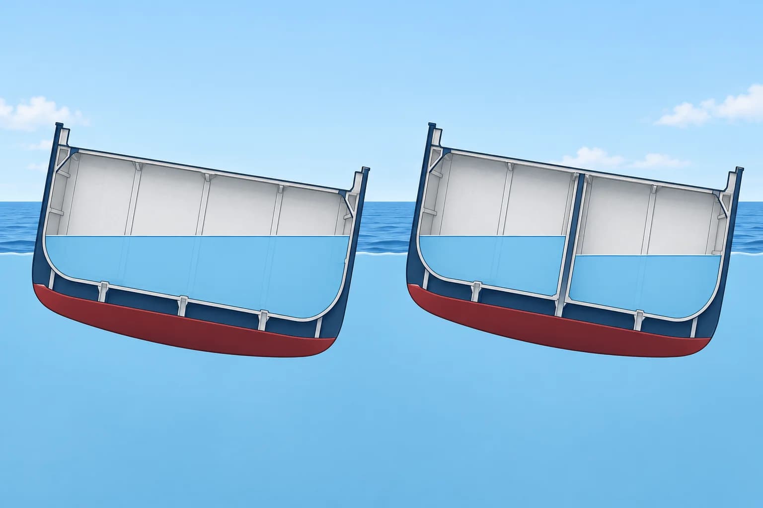
On a ship
You know the idea from yacht stability: slack liquid moves to the low side and acts like a rise of G. On a ship you work it in numbers. Each tank's free surface moment, FSM, comes from the tank tables. The free surface correction is FSC = ΣFSM ÷ Δ, in metres, and GM fluid = GM solid − FSC.
The FSM
FSM = i × ρ, in t·m, where i is the transverse moment of inertia of the liquid surface in m⁴ and ρ the liquid's density in t/m³. For a rectangular surface, i = l × b³ ÷ 12, l along the ship and b across. Tank tables list i, or FSM at a stated density: scale by the density ratio for another liquid.
Subdivision
A liquid-tight lengthwise division into n equal parts divides the combined i by n²: both halves slack give a quarter; one gives an eighth. That is why double bottoms are split port and starboard. In a rectangular, vertical-sided tank, while the surface spans its full length and breadth, FSM is independent of liquid quantity. Its height in the ship does not affect FSM.
What to count
Under the Intact Stability (IS) Code, Part B 3.1, correct tanks below 98% full. Nominally full cargo tanks still need correction: follow the approved stability booklet. For each type of consumable liquid, such as fuel or fresh water, include at least the transverse pair or centre tank with the greatest free-surface effect. Omit small tanks only where the booklet permits it under 3.1.12; do not judge from upright FSM alone.
Good practice
Keep slack tanks to a minimum and work them one at a time. For fixed levels, use actual filling. For variable levels, use the greatest correction within the planned range unless the approved booklet permits stage-by-stage values. Ballast operations must cover the worst intermediate stage.
Key figures
- Free surface moment
- FSM (t·m) = i × ρ
- Rectangular surface
- i = l × b³ ÷ 12 (m⁴)
- Free surface correction
- FSC (m) = ΣFSM ÷ Δ
- Effective GM
- GM fluid = GM solid − FSC
- n equal divisions
- Combined i ÷ n²; both halves slack: ¼, one half: ⅛
- When to count it
- Non-cargo, no exemption: below 98%; cargo: follow booklet
Worked example: GM fluid from the tank tables
- Data: Δ 15,000 t, KM 8.40 m, solid KG 7.70 m; two slack tanks. — GM solid = 8.40 − 7.70 = 0.70 m.
- Ballast tank table: i = 1,250 m⁴. FSM = 1,250 × 1.025 = 1,281 t·m. — Use the supplied table inertia and the ballast density, 1.025 t/m³.
- Fuel tank table: FSM = 900 t·m at density 0.90 t/m³. At 0.95 t/m³, use 900 × 0.95 ÷ 0.90 = 950 t·m. — This supplied table entry needs scaling by the density ratio.
- FSC = (1,281 + 950) ÷ 15,000 = 0.149 m. — Total FSM divided by the displacement.
- GM fluid = 0.70 − 0.149 = 0.55 m. — Use 0.55 m for initial stability and small-angle list calculations.
- If the rectangular ballast tank is divided liquid-tight lengthwise into equal halves, both slack total 1,281 ÷ 4 = 320 t·m. — n² rule: with the fuel tank still slack, FSC falls to 0.085 m.
Remember
- FSM = i × ρ; for a rectangle, i = l × b³ ÷ 12.
- FSC = ΣFSM ÷ Δ and GM fluid = GM solid − FSC.
- Lengthwise division into n equal parts divides combined FSM by n², with all parts slack.
- Non-cargo, no exemption: count below 98%. Cargo: follow the booklet. Include the worst consumable tanks.
- Keep slack tanks few and work them one at a time.
Common mistakes
Wrong: A tank nearly empty has a small free surface effect.
Right: In a rectangular, vertical-sided tank, while the surface spans its full length and breadth, FSM stays the same at a fixed density.
Wrong: Use the sea-water density for every tank.
Right: Use the density of the liquid in the tank, such as fuel at about 0.95 t/m³.
Wrong: Divide ΣFSM by the lightship weight.
Right: Divide by the displacement of the condition you are checking.
Worked case
In port the ship's GM solid is 0.40 m at Δ 12,000 t. You plan to run a rectangular 20 m × 12 m sea-water ballast tank slack during cargo work. What does it cost in GM, and what would you suggest?
Show the answer
FSM = 20 × 12³ ÷ 12 × 1.025 = 2,952 t·m; FSC = 2,952 ÷ 12,000 = 0.246 m. GM fluid is 0.154 m. Keep the tank full or empty under the approved plan. If it already has a liquid-tight lengthwise division, one slack half contributes 369 t·m (one eighth); both slack halves total 738 t·m (one quarter). Include every other slack tank and recheck the whole condition before cargo work.
Practice question
A rectangular tank is 20 m long and 12 m wide, slack with sea water of 1.025 t/m³. What is its FSM?
- 2,880 t·m
- 246 t·m
- 8,856 t·m
- 2,952 t·m
Show the answer
Answer: D. i = 20 × 12³ ÷ 12 = 2,880 m⁴; FSM = 2,880 × 1.025 ≈ 2,952 t·m. 2,880 forgets the density; 246 uses b².