
Ship stability and stowage · Level P3 · 5 parts · about 18 min
Centre of gravity and metacentric height (GM)
5 short parts: KG, KM and GM · Moments · Shifting weights · Heavy lifts · Inclining test. Each part explains the idea, then gives the points to remember, the common mistakes, a worked case and a practice question; the Academy unit adds all 27 check questions.
1 · KG, KM and GM
KG, KM and GM on a ship
KM comes from hull shape and draught, KG from loading. Correct for free surface, then follow the booklet’s instructions to compare with its limits.
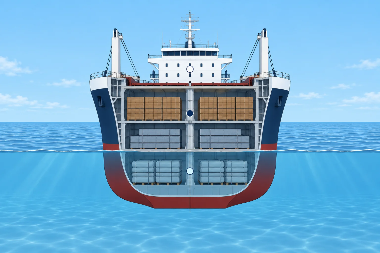
Three heights
All heights are measured from the keel, K. KM, the height of the metacentre M, comes from the hydrostatic table at the ship's draught. KG, the height of the centre of gravity G, comes from your loading calculation. GM = KM − KG. You met them in yacht stability; on a ship you work them out from tables and moments.
Solid and fluid
GM from the weights alone is solid GM. A slack tank is partly full. Its liquid reduces effective GM. Read its free surface moment (FSM), in t·m, from the tank table. Σ means add the tank values; Δ is displacement in tonnes. The free surface correction is FSC = ΣFSM ÷ Δ. KG fluid = KG + FSC; GM fluid = KM − KG fluid. Follow the booklet’s instructions when comparing these values with its limits.
Is it enough?
Read the booklet instructions for its minimum GM or maximum KG curve. Check whether the limits include free surface or require your corrected value. Compare like with like, within the approved operating range. Never apply free surface twice. These examples use limits requiring fluid values. The general IS Code GM minimum of 0.15 m is only one requirement, not your sailing target.
Can it be too much?
A large GM makes the ship stiff, with a short, violent roll. That strains lashings, can shift cargo and wears out the crew. Ore-loaded bulk carriers can have several metres of GM. Some booklets give a maximum GM too, for example for containers or timber deck cargo.
Where errors come from
Lightship includes fixed ballast, machinery operating fluids and fixed firefighting agents. It excludes cargo, consumable liquids, ballast water, stores, people and effects. A wrong lightship KG, a forgotten weight or a missed FSM can each move KG by many centimetres. The ship’s constant is the difference between measured displacement and accounted-for weights. Include its documented weight at a justified height. Check tank soundings and densities, and compare your answer with the last similar voyage and the loading computer.
Key figures
- GM
- KM − KG
- Free surface correction
- FSC = ΣFSM ÷ Δ
- Fluid GM
- KM − (KG + FSC)
- IS Code minimum
- GM0 ≥ 0.15 m, together with all other criteria
Worked example: GM in the departure condition
- Data: Δ 15,000 t at 8.00 m. Table KM = 8.40 m. Loading table KG = 7.70 m. — KM from the hull, KG from the weights.
- Solid GM = 8.40 − 7.70 = 0.70 m. — Before free surface.
- Slack tanks: ΣFSM = 2,231 t·m. FSC = 2,231 ÷ 15,000 = 0.149 m. — From the tank tables.
- KG fluid = 7.849 m; GM fluid = 8.40 − 7.849 = 0.551 m, say 0.55 m. — Fluid value for these examples.
- The booklet’s minimum fluid GM at 8.00 m is 0.35 m: margin 0.20 m. — Read the curve at this draught, not a fixed value.
Remember
- GM = KM − KG: KM from the table at the draught, KG from the moments.
- Calculate KG fluid = KG + ΣFSM ÷ Δ; use the booklet’s stated comparison basis.
- Read the booklet’s GM or KG limit at the actual draught; check its free-surface allowance and operating range.
- Too much GM is a problem too: violent rolling and high lashing loads.
Common mistakes
Wrong: GM 0.15 m is enough because it meets the IS Code.
Right: 0.15 m is only one criterion. The booklet's limit curve covers all of them and is usually higher.
Wrong: KM stays the same however you load.
Right: KM depends on draught. After loading or discharging, read KM again at the new draught.
Worked case
After loading, KG is 7.95 m and ΣFSM is 1,500 t·m at Δ 15,000 t, draught 8.00 m, KM 8.40 m. The booklet’s maximum fluid KG at this draught is 8.05 m. Can you sail?
Show the answer
FSC = 0.10 m, so fluid KG = 8.05 m and fluid GM = 0.35 m. This meets the stated departure limit exactly, with no margin. Seek more margin and recalculate displacement, KM, KG and FSC after any loading or tank change. Sailing still requires all other checks. Calculate arrival and intermediate conditions too: fuel use changes KG, KM and free surface, so arrival can improve or worsen.
Practice question
KM 9.20 m, KG 8.40 m, ΣFSM 1,200 t·m, Δ 12,000 t. What is GM fluid?
- 0.80 m
- 0.70 m
- 0.90 m
- 0.10 m
Show the answer
Answer: B. FSC = 1,200 ÷ 12,000 = 0.10 m; GM fluid = 9.20 − 8.40 − 0.10 = 0.70 m.
2 · Moments
Loading and discharging: moments about the keel
List every weight with its height above the keel, add up weights and moments, and divide. That gives KG for any loading condition.
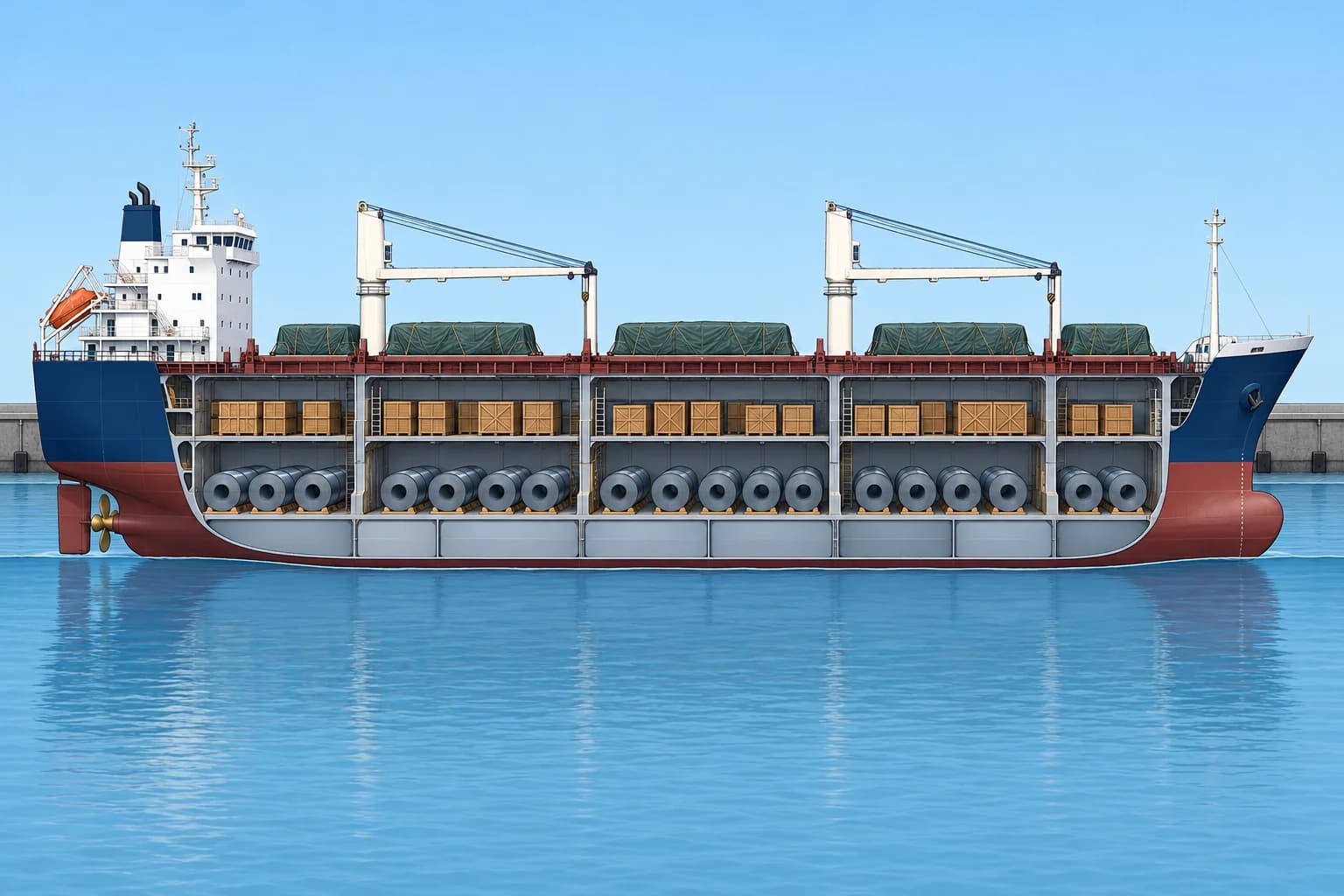
The method
Each weight w has its own centre at a height Kg above the keel. Its vertical moment is w × Kg, in t·m. Add all the weights to get Δ and all the moments to get the total moment: KG = Σ(w × Kg) ÷ Σw. Start with lightship from the booklet, then add cargo, fuel, water, stores, ballast and the constant.
Loading and discharging
To load, add a line with the new weight and its moment. To discharge, enter the weight and its moment as negative values. The totals give the new Δ and KG. G moves towards a weight you load and away from a weight you discharge.
Then the hydrostatics
The new Δ gives a new draught, and so a new KM from the table. GM = new KM − new KG. Do not assume KM is unchanged: it can change by several centimetres between draughts.
Free surface
Add the free surface effect at the end. Many forms add ΣFSM to the total moment, then divide by Δ: KG fluid = (Σ moments + ΣFSM) ÷ Δ. That is the same as KG + ΣFSM ÷ Δ. Use the FSM of every tank that is slack in that condition.
Checking your work
A capacity plan gives the centre of the full space, not necessarily the centre of your cargo. Use the actual stowage distribution for cargo and the tank tables at the actual filling level for liquids. A partly filled hold need not be filled evenly from the bottom. Compare your answer with a similar past voyage and the loading computer.
Key figures
- Vertical moment
- w × Kg (t·m)
- KG
- Σ(w × Kg) ÷ Σw
- Discharging
- Negative weight and negative moment
- Fluid KG
- (Σ moments + ΣFSM) ÷ Δ
Worked example: the loading table
- Lightship 4,500 t × 8.13 m = 36,585 t·m. Fuel, water and stores 950 t × 3.10 m = 2,945 t·m. — Lightship from the booklet's inclining result.
- Lower holds 6,600 t × 6.52 m = 43,032 t·m; intermediate cargo decks ('tween decks) 2,500 t × 10.40 m = 26,000 t·m; deck 450 t × 15.40 m = 6,930 t·m. — Each cargo at its own centre.
- Totals 15,000 t and 115,492 t·m: KG = 115,492 ÷ 15,000 = 7.70 m. — Moments divided by weights.
- Load 500 t of deck cargo at Kg 11.00 m: 15,500 t and 120,992 t·m, KG = 7.806 m. — G rises towards the new weight.
- At Δ 15,500 t, the supplied hydrostatic data give draught 8.20 m and KM 8.38 m. Solid GM = 8.38 − 7.806 = 0.574 m. — Read KM again at the new draught.
- FSC = 2,231 ÷ 15,500 = 0.144 m. GM fluid = 0.574 − 0.144 = 0.43 m. — Down from 0.55 m: deck cargo is costly.
Remember
- KG = Σ(w × Kg) ÷ Σw, starting from lightship.
- Discharged weights go in as negative weights and moments.
- Read KM at the new draught, then add the free surface effect.
- Use actual cargo centres and tank centres at the measured filling level.
Common mistakes
Wrong: When discharging, subtract the weight from Δ but keep the total moment.
Right: Subtract its moment too, w × Kg, or KG comes out wrong.
Wrong: The capacity plan centre fits any amount of cargo in a hold.
Right: The full-space centre need not match the cargo centre. Calculate from the actual stowage.
Worked case
From 15,000 t and 115,492 t·m, you discharge 300 t at Kg 6.30 m. A colleague says the lighter ship must now have more GM. Do you agree?
Show the answer
New Δ = 14,700 t. New moment = 115,492 − 300 × 6.30 = 113,602 t·m. KG = 113,602 ÷ 14,700 = 7.728 m. KG rises because the removed cargo was below G. Less displacement does not prove more GM. Read KM at the new draught, recalculate FSC and compare fluid GM with the booklet limit on its stated basis.
Practice question
Δ 10,000 t, KG 7.00 m. You load 1,000 t at Kg 4.00 m. What is the new KG?
- 6.700 m
- 7.300 m
- 6.727 m
- 6.400 m
Show the answer
Answer: C. (70,000 + 4,000) ÷ 11,000 = 6.727 m.
3 · Shifting weights
Shifting weights: vertical, transverse and both at once
Moving a weight already aboard moves G parallel to the move by w × d ÷ Δ. Vertical moves change GM; transverse moves cause a list.
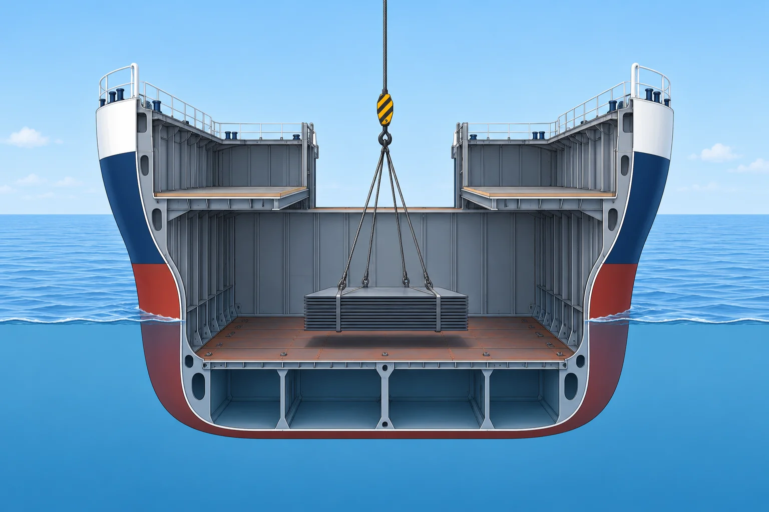
The rule
GG′ = w × d ÷ Δ, parallel to the move. For the small transverse and vertical shifts here, with no fore-and-aft move, treat mean draught and upright KM as unchanged. Δ stays constant. A fore-and-aft shift needs a separate trim check. Ballast transfers also change free surface while tanks are slack.
Vertical moves
Moving weight up raises G by w × d ÷ Δ and cuts GM by the same amount. Moving it down does the opposite. Shifting cargo from a tween deck to the lower hold, or landing a heavy lift on the tank top, the floor above the bottom tanks, instead of on deck, gains GM without changing Δ.
Transverse moves
Moving weight across moves G off the centreline by GGH = w × d ÷ Δ. With positive GM she lists until B, the centre of buoyancy, lies vertically below G: tan θ = GGH ÷ GM fluid, for small angles. Finding and correcting a list in detail belongs to the Trim unit.
Diagonal moves
A weight moved up and across moves G both ways. Split the move into its vertical and horizontal parts and apply the rule to each. Find the new GM from the vertical part first, then use it to find the list from the horizontal part.
Pumping ballast
Transferring ballast is a shift of weight, but the tanks pass through slack stages. During the transfer both may be slack, adding FSM. Transfer when GM has a margin, and keep the number of slack tanks small.
Key figures
- Shift of G
- GG′ = w × d ÷ Δ, parallel to the move
- Vertical shift
- Change of GM = w × d ÷ Δ
- List from a transverse shift
- tan θ = GGH ÷ GM fluid (small angles)
- Diagonal shift
- Vertical part first, then the list
Worked example: a diagonal shift
- Data: Δ 15,000 t, GM fluid 0.55 m, upright. In one hold, 150 t moves 4 m up and 6 m to port, with no fore-and-aft move or free-surface change. — One move, two components.
- Vertical: GG′ = 150 × 4 ÷ 15,000 = 0.04 m. New GM fluid = 0.51 m. — G rises; GM falls by the same amount.
- Horizontal: GGH = 150 × 6 ÷ 15,000 = 0.06 m to port. — G moves off the centreline.
- tan θ = 0.06 ÷ 0.51 = 0.118, so θ ≈ 6.7° to port. — Use the new GM.
- With the old GM of 0.55 m you would get only 6.2°. — The rise of G makes the same shift list her more.
Remember
- GG′ = w × d ÷ Δ. Here, no fore-and-aft move; Δ, mean draught and upright KM stay unchanged.
- Moving weight up costs GM one for one.
- List: tan θ = GGH ÷ GM fluid.
- Diagonal shifts: vertical part first, then the list with the new GM.
Common mistakes
Wrong: A ballast transfer between tanks is just a shift, so stability cannot drop.
Right: During the transfer the tanks are slack: free surface lowers GM until each is full or empty again.
Wrong: Use the original GM to find the list after a diagonal shift.
Right: Apply the vertical part first. Moving up reduces GM; moving down increases it. Use that new GM to calculate the list.
Worked case
You can move 200 t of steel from Kg 10.0 m to Kg 4.0 m within the same hold, on the centreline, with no free-surface change. Δ is 15,000 t and fluid GM is 0.47 m; the booklet requires 0.60 m. Does this shift make the condition acceptable?
Show the answer
G falls by 200 × 6 ÷ 15,000 = 0.08 m, so fluid GM rises to 0.55 m. That still misses the 0.60 m limit by 0.05 m: the move helps but is insufficient. Plan another suitable change and recheck the condition before sailing. Secure the steel in its new position.
Practice question
Δ 12,000 t. 240 t is moved 5 m down. What happens to GM?
- It decreases by 0.10 m
- It increases by 0.02 m
- It increases by 1.00 m
- It increases by 0.10 m
Show the answer
Answer: D. GG′ = 240 × 5 ÷ 12,000 = 0.10 m down, so GM rises 0.10 m.
4 · Heavy lifts
Suspended weights and heavy lifts with ship's gear
Lifted weight acts at the suspension point. Check heel and GM throughout the lift; head height, outreach and ballast can change the worst stage.
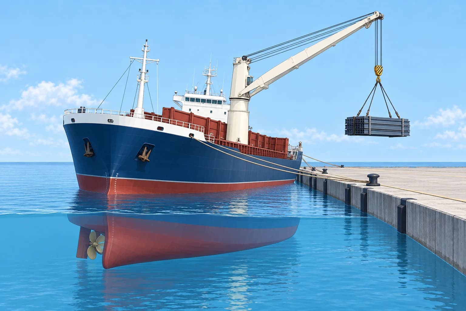
Where it acts
For a load already aboard, its weight acts at the point of suspension, the crane or derrick head, as soon as it hangs clear of the deck or tank top. G rises by w × (head height − load’s Kg) ÷ Δ. This onboard-shift formula applies whether the load hangs 1 m or 10 m above the deck.
Two effects
The rise of G reduces GM. For a load already aboard, G moves transversely by w × (head position − original load position) ÷ Δ. Measure both positions from the centreline, with a consistent sign for each side. Crane outreach, the radius from its pedestal, may differ. Check every stage for head height, offset, ballast and movement of the crane’s own G. Include changes in the crane’s own weight moments.
Lifting from the quay
Loading from shore adds the weight at the head: Δ grows by w. Use the loading-by-moments method with the new displacement and added moments. The already-aboard shift formulas do not apply. For discharge, calculate the hanging condition, then remove the load’s weight and moment when it is released ashore. Check the whole sequence before you start.
Preparing
The IS Code added lifting provisions in 2020, with ship-date and operation thresholds. Confirm applicability with your flag-state authority and classification society (class). Use your approved booklet and crane-manual limits. Deal with slack tanks, plan any counter-ballast, and tend the moorings so a sudden heel cannot part them. This list formula is a small-angle estimate with positive fluid GM; use the approved lifting assessment for acceptance.
During the lift
Lift slowly, stop the load swinging and keep people clear. Watch the inclinometer, which shows the heel angle. If she lists more than planned, stop and land the load safely. Do not improvise ballast changes; follow the approved lift and ballast sequence.
Key figures
- Rise of G: load already aboard
- w × (head height − load Kg) ÷ Δ
- Transverse shift: load already aboard
- w × (xhead − xload) ÷ Δ; positions from centreline
- List
- tan θ ≈ GGH ÷ GM fluid; small angles, positive GM
- Worst stage
- Worst calculated stage, including full outreach
Worked example: lifting a package out of the hold
- Data: Δ 15,000 t, GM fluid 0.55 m, initially upright. A 60 t package starts on the centreline at Kg 3.0 m. The crane head stays 25.0 m above the keel; ballast is unchanged. — The package is already included; initially centred. Assume the crane’s own moments stay unchanged in this simplified example.
- Rise of G = 60 × (25.0 − 3.0) ÷ 15,000 = 0.088 m. GM = 0.55 − 0.088 = 0.462 m. — As soon as it leaves the tank top.
- At maximum head offset, 15 m from the centreline: GGH = 60 × (15 − 0) ÷ 15,000 = 0.060 m. — G moves towards the head.
- Small-angle estimate: tan θ ≈ 0.060 ÷ 0.462 = 0.130, θ ≈ 7.4°. — The worst list here: fixed head height, unchanged ballast and crane moments, maximum head offset.
- Compare with the crane manual and booklet limits. If excessive, revise the lift or approved counter-ballast plan and recalculate every stage before lifting. — Check intermediate stages and both end conditions.
Remember
- A suspended load acts at the point of suspension as soon as it leaves the deck.
- Check every lift stage; full outreach and minimum GM may occur at different stages.
- Prepare: slack tanks dealt with, counter-ballast planned, moorings tended.
- Stop and land the load if the list goes beyond the plan.
Common mistakes
Wrong: While the load is only just above the deck it barely affects stability.
Right: Its weight acts at the head the moment it leaves the deck. The rise of G is the same at 1 m or 10 m.
Wrong: Improvise ballast changes to chase an unexpected list while the load hangs.
Right: Counter-ballast can heel the ship the other way when the load is released or suddenly lost. Use the approved sequence and verify that failure condition.
Worked case
Using the example values, the lift gives about 7.4° but the plan allows 5°. Can you proceed unchanged? Estimate the opposing ballast moment and say what must be checked before lifting.
Show the answer
Small-angle estimate, ignoring changes in the crane’s own moments: the lift gives 900 t·m. At 5°, 15,000 × 0.462 × tan 5° allows about 606 t·m: 294 t·m opposing, say 300. Shifting 25 t through 12 m supplies this only if KG and FSC stay unchanged. Check tank centres, FSC, all stages and both end conditions. Also verify sudden hook-load loss with counter-ballast still in place.
Practice question
Δ 10,000 t. A 50 t load on deck at Kg 12 m is lifted by a crane with its head at 30 m. How far does G rise?
- 0.09 m
- 0.15 m
- 0.06 m
- 0.90 m
Show the answer
Answer: A. 50 × (30 − 12) ÷ 10,000 = 0.09 m. Using 30 m alone gives 0.15 m.
5 · Inclining test
The inclining experiment: finding lightship KG
Move known weights across, measure the heel and work out GM. From that comes the lightship KG that starts every loading calculation.
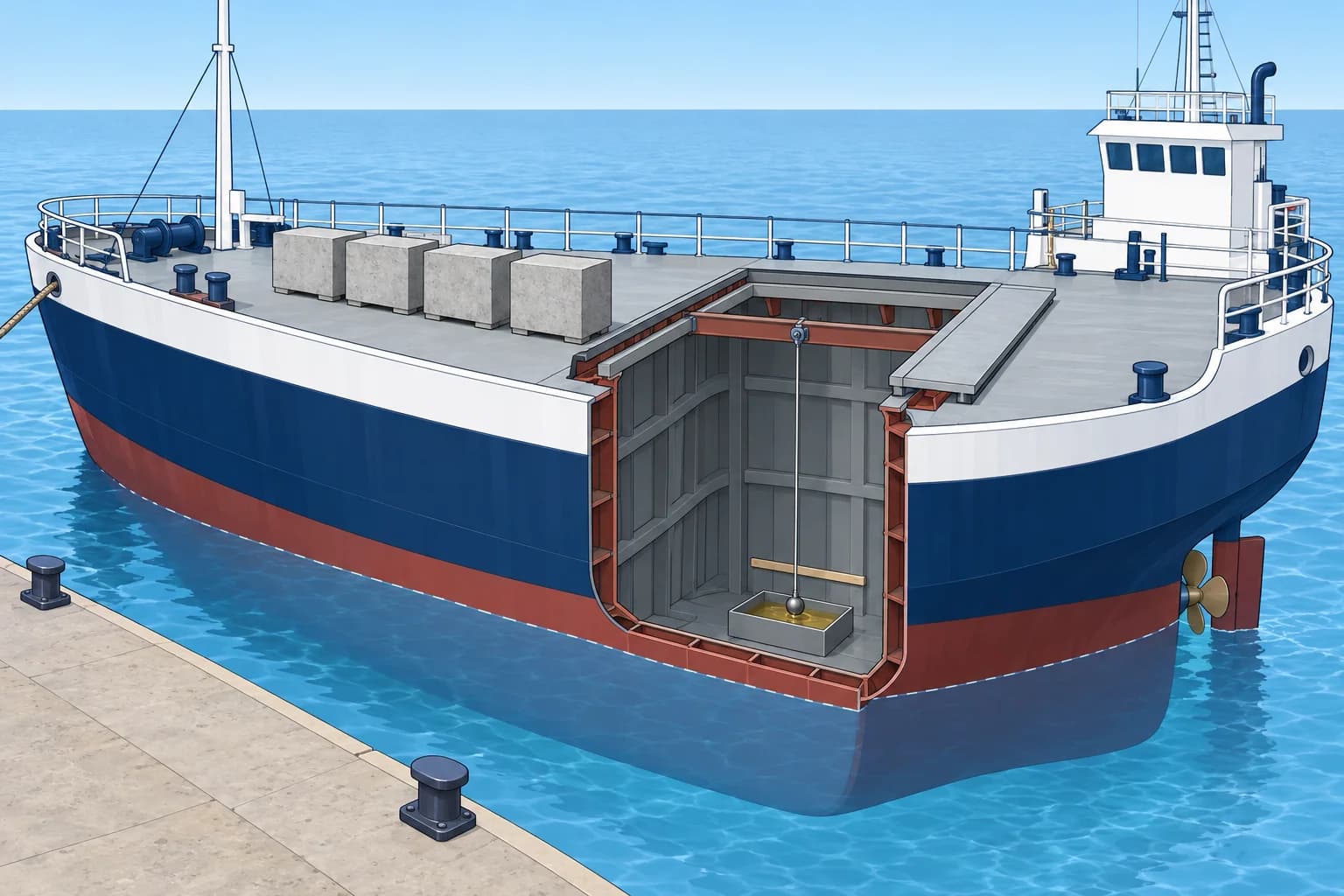
Why
Passenger ships and cargo ships of 24 m or longer are normally inclined on completion; the Administration, the flag-state authority, may permit exemptions. After corrections, the test gives lightship displacement and KG. Passenger ships need a lightweight survey, a check of lightship weight and centres, at least every five years. Re-incline if lightship displacement changes by more than 2% or its fore-and-aft centre of gravity (LCG) by more than 1% of the applicable defined length L. Material alterations require updated stability information and re-inclining where necessary.
The principle
Moving a known weight w across distance d gives GM measured = w × d ÷ (Δ × tan θ). This is fluid GM if tanks are slack. Add FSC = ΣFSM ÷ Δ to obtain solid GM, then KG = KM − GM solid. Read KM from hydrostatics for the test draught and actual trim. With no free surface, measured and solid GM are equal.
Measuring the heel
Pendulums, at least two and preferably three, hang in sheltered places: tan θ = deflection ÷ pendulum length. Each should deflect at least 15 cm to each side, which usually needs 3 m or more of wire. The weights should heel her between 1° and 4° each side. The Administration may approve alternative heel-measuring instruments.
Conditions
The ship should be nearly complete, in calm water, clear of the bottom and quay, with slack moorings and everyone at recorded stations. Keep tanks empty or pressed up (completely full); quantify any remaining free surface. Read draughts on both sides and measure dock-water density to establish Δ; use hydrostatics for the actual trim. The standard test uses eight weight movements. Plot readings to check consistency; investigate departures from a straight line.
From test to lightship
Lightship includes fixed ballast, machinery operating fluids and fixed firefighting agents. It excludes cargo, consumable liquids, ballast water, stores, people and effects. The test condition includes test weights, people and items not part of lightship, and may lack items still to be fitted. The lightweight survey lists them. Find solid test KG first. Remove extra items or add missing ones by moments to obtain lightship weight and KG for the booklet.
Key figures
- Measured GM
- w × d ÷ (Δ × tan θ)
- Pendulum
- tan θ = deflection ÷ length; ≥ 15 cm each side
- Heel in the test
- 1° to 4° each side
- Inclined on completion: normally; exemptions apply
- Passenger ships; cargo ships of 24 m and over
- Passenger ships
- Survey ≤5 years; re-incline: Δ change >2%, LCG change >1% of L
Worked example: the inclining result
- Test displacement 4,520 t includes 20 t of test weights at Kg 12.0 m. Move them 15 m across. Free surface is zero; the test weights are the only difference from lightship. — w × d = 300 t·m.
- A 5.0 m pendulum deflects 0.255 m: tan θ = 0.255 ÷ 5.0 = 0.051 (θ ≈ 2.9°). — Within 1–4°, more than 15 cm of deflection.
- Measured GM = 20 × 15 ÷ (4,520 × 0.051) = 1.30 m. FSC = 0, so solid GM = 1.30 m. — Measured and solid GM are equal in this test condition.
- KM at the test draught is 9.45 m: solid test KG = 9.45 − 1.30 = 8.15 m. — Use solid GM to find the actual test-condition KG.
- Remove the test weights at Kg 12.0 m: KG = (4,520 × 8.15 − 20 × 12.0) ÷ 4,500 = 8.13 m. — Lightship 4,500 t, KG 8.13 m: the first line of every loading table.
Remember
- GM measured = w × d ÷ (Δ × tan θ). Add FSC for solid GM; KG = KM − GM solid.
- At least two pendulums, 15 cm or more of deflection, 1–4° each side.
- Tanks empty or pressed up, calm water, slack moorings, nobody moving.
- Correct to lightship by moments for items aboard or missing.
Common mistakes
Wrong: The test KG is the lightship KG.
Right: The test condition includes weights and items that are not lightship. Correct them out by moments.
Wrong: A tiny heel, half a degree, is more accurate.
Right: Small angles give small, error-prone deflections. Aim for 1–4° each side.
Worked case
During an inclining test a fuel tank turns out to be one-third full, not empty, and a crew member walks across the deck while a reading is taken.
Show the answer
Stop readings and return everyone to their recorded positions. Ask the test supervisor to confirm that the tank’s weight, centre and free-surface correction are reliable throughout the test heel range. If accepted, add FSC to measured GM before finding test KG and correct to lightship by moments; repeat the disturbed movement. Otherwise empty or press up the tank, re-establish displacement and centres, then restart the measurement series.
Practice question
30 t is moved 12 m across, Δ 6,000 t, tan θ = 0.05. What is measured GM?
- 0.60 m
- 1.20 m
- 2.40 m
- 0.83 m
Show the answer
Answer: B. Measured GM = 30 × 12 ÷ (6,000 × 0.05) = 360 ÷ 300 = 1.20 m. Add FSC if you need solid GM.