
Ship stability and stowage · Level P3 · 5 parts · about 19 min
The GZ curve and the stability criteria (2008 IS Code)
5 short parts: Small angles · Cross curves · Ship's GZ curve · IS Code criteria · Weather criterion. Each part explains the idea, then gives the points to remember, the common mistakes, a worked case and a practice question; the Academy unit adds all 32 check questions.
1 · Small angles
GZ at small angles and the wall-sided formula
Near upright, GZ ≈ GM × sin θ. It is a good start, but the real curve soon leaves it, so know where the shortcut ends.
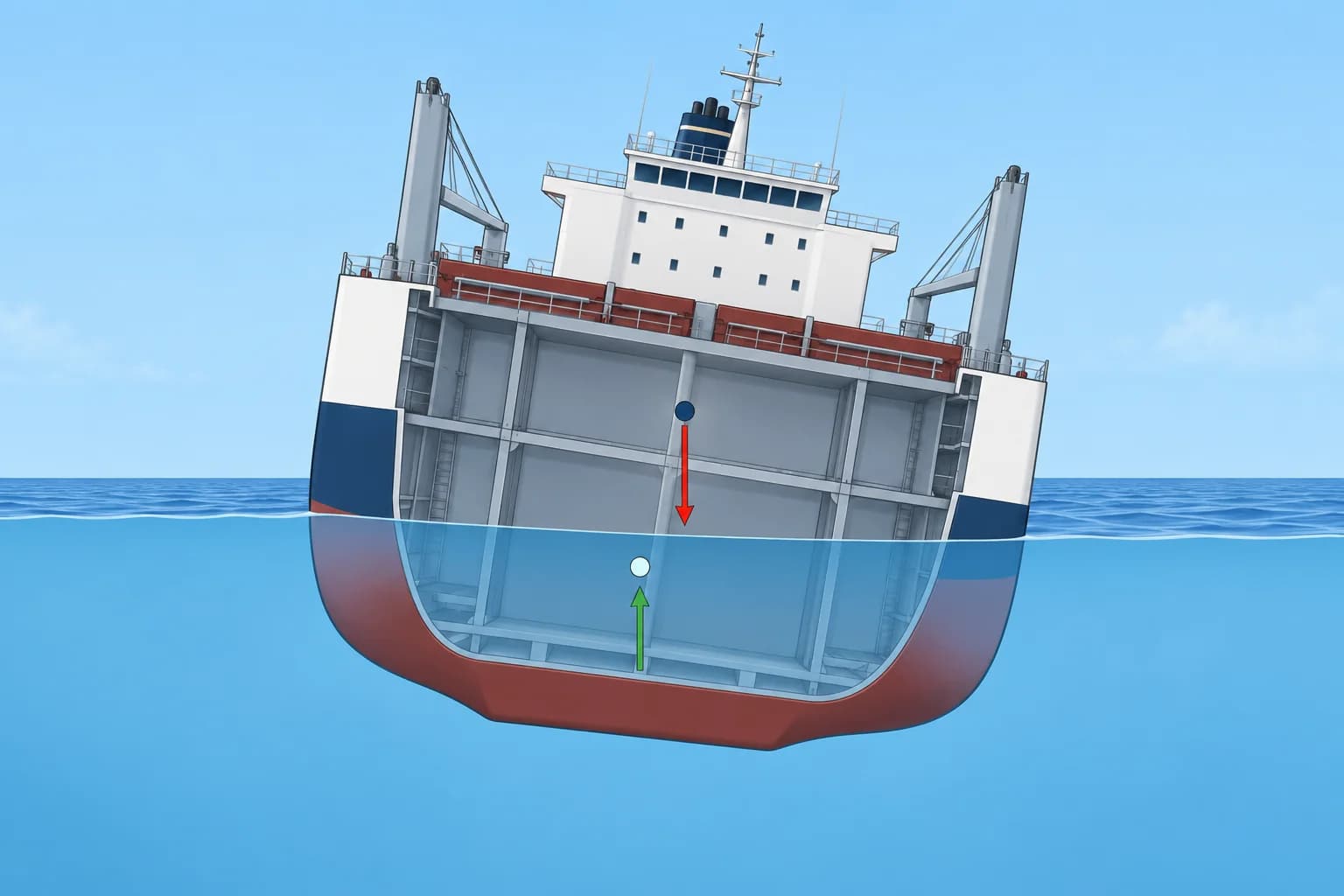
From yacht to ship
You already know that GZ ≈ GM × sin θ at small heel. On a ship you use the same idea with booklet numbers. Displacement Δ and KM come from the hydrostatic tables, and KG from your table of moments. Use GM fluid, the metacentric height after the free surface correction. The righting moment is Δ × GZ, in t·m.
Why the shortcut stops working
GM × sin θ assumes the metacentre M stays fixed. That is close enough for only a few degrees, usually quoted as up to about 7–10°. Beyond that the waterplane changes shape, B no longer moves on a circle, and M moves. The real GZ can then be larger or smaller than GM × sin θ.
The wall-sided formula
A wall-sided ship has vertical sides where the waterline moves as she heels. For her, a better lever is GZ = sin θ × (GM + ½ × BM × tan² θ). BM is the height of M above B, or KM − KB. It holds only until the deck edge immerses or the bilge comes out of the water. Do not use it where the sides slope outward or inward at the moving waterline.
Conditional wall-sided comparison
Assume vertical sides throughout the moving waterline. Take GM 0.55 m and BM 5.0 m. At 10°, GM × sin θ gives 0.096 m and the wall-sided formula 0.109 m. At 20° they give 0.188 m and 0.301 m. These comparison values are not our ship’s approved GZ values. Her deck edge immerses at 18°, so the 20° wall-sided result is outside the formula’s limit.
Righting moment
GZ is a length; the ship's resistance to heeling is a moment. A ship of 15,000 t with GZ 0.096 m at 10° has a righting moment of about 1,440 t·m. For a static balance, compare the heeling moment with this righting moment; during a roll, motion can carry her farther.
Key figures
- Small-angle lever
- GZ ≈ GM × sin θ, up to about 7–10°
- Righting moment
- RM = Δ × GZ (t·m)
- Wall-sided formula
- GZ = sin θ × (GM + ½ × BM × tan² θ)
- BM
- BM = KM − KB
- Wall-sided limit
- Until the deck edge immerses or the bilge emerges
Remember
- GZ ≈ GM × sin θ works for a few degrees only, about 7–10°.
- Use GM fluid, corrected for free surface, in every lever and moment.
- Righting moment = Δ × GZ in t·m.
- The wall-sided formula adds ½ × BM × tan² θ and holds until deck edge immersion or bilge emergence.
- For any larger angle, use the booklet's cross curves.
Common mistakes
Wrong: GM tells you how stable the ship is at 30°.
Right: GM describes only the start of the curve. At 30° use GZ from the cross curves.
Wrong: The wall-sided formula works at any angle.
Right: It assumes vertical sides at the waterline. It fails once the deck edge immerses or the bilge emerges.
Wrong: Use the solid GM because it is the ship's real GM.
Right: Slack tanks reduce effective GM. Use GM fluid for levers, moments and criteria.
Worked case
Your ship displaces 15,000 t with GM fluid 0.55 m. The second officer estimates the righting lever at 25° as 0.55 × sin 25° = 0.23 m and says the ship is fine. What do you tell him?
Show the answer
GM × sin θ is only a small-angle estimate, so 0.23 m at 25° is not reliable. Use the approved booklet's GZ curve for this loading condition. One estimated lever cannot establish that the ship is safe. The next part shows how to obtain the correct levers.
Practice question
Δ is 15,000 t, GM solid 0.70 m and GM fluid 0.55 m. About what is the righting moment at 10°?
- About 8,250 t·m
- About 1,820 t·m
- About 1,430 t·m
- About 14,300 t·m
Show the answer
Answer: C. RM = Δ × GM fluid × sin θ = 15,000 × 0.55 × 0.174 ≈ 1,430 t·m. 8,250 forgets sin θ; 1,820 uses solid GM.
2 · Cross curves
Cross curves (KN) and building the GZ table
The cross curves give KN for each heel and displacement. Subtract KG × sin θ and you have the GZ curve for this loading condition.
Why KN
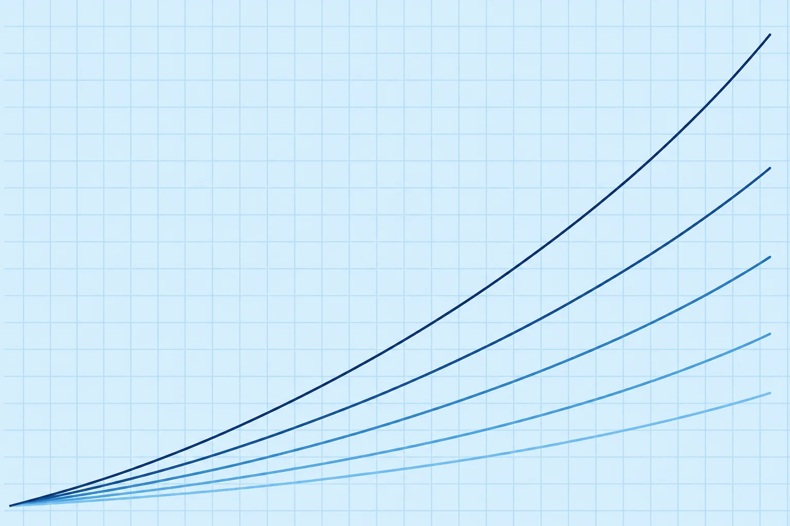
The naval architect cannot know your KG in advance. So the booklet gives KN, the righting lever measured from the keel point K, as if G were at K. KN depends on hull form, displacement and heel, and strictly on trim. Curves or tables of KN against displacement, one line per heel angle, are the cross curves of stability (pantocarenas in Spanish).
From KN to GZ
G lies KG above K. When the ship heels θ, the lever lost to the height of G is KG × sin θ. So GZ = KN − KG × sin θ. Use the fluid KG: solid KG plus the free surface correction (FSC), ΣFSM ÷ Δ. Here ΣFSM is the sum of the tanks' free surface moments, in t·m. With the solid KG every GZ comes out too large.
Reading the tables
Enter the cross curves with the condition's displacement and interpolate between rows. Read KN at each tabulated angle, often every 10° from 10° to 60° or more. Some booklets tabulate levers for an assumed KG instead of K. Then GZ = GZ assumed + (KG assumed − KG) × sin θ. Read the booklet's note on its datum.
Plot and check
Plot GZ against heel and draw a smooth curve. Draw its tangent at 0°. Extended to 57.3° (one radian), that tangent should reach the fluid GM. Check the slope at the origin, not the curve’s distance above the line at larger angles.
Trim matters
Cross curves are computed for a stated trim, or with the ship free to trim as she heels. At a large trim the levers can differ. An approved loading computer calculates them for your actual draughts; by hand, use the trim tables the booklet provides.
Key figures
- GZ from KN
- GZ = KN − KG × sin θ (fluid KG)
- Fluid KG
- KG fluid = KG solid + ΣFSM ÷ Δ
- Assumed-KG tables
- GZ = GZ assumed + (KG assumed − KG) × sin θ
- Start check
- Tangent at 0° reaches GM at 57.3° (1 rad)
- KN depends on
- Hull form, displacement, heel and trim; not on KG
Worked example: GZ table from the cross curves
- Data: Δ 15,000 t, KM 8.40 m, solid KG 7.70 m, ΣFSM 2,231 t·m. — FSC ≈ 0.15 m; fluid KG = 7.70 + 0.15 = 7.85 m; fluid GM = 0.55 m. Use these rounded values throughout.
- Read KN at 15,000 t: 10° 1.46, 20° 2.92, 30° 4.33, 40° 5.47, 50° 6.31, 60° 6.90 m. — Interpolate between displacement rows where needed.
- Work out 7.85 × sin θ: 1.363, 2.685, 3.925, 5.046, 6.013, 6.798 m. — The same fluid KG at every angle.
- Subtract: GZ = 0.097, 0.235, 0.405, 0.424, 0.297, 0.102 m. — The lever at each heel for this condition.
- Check the start: GM = 8.40 − 7.85 = 0.55 m; 0.55 × sin 10° = 0.096 m. — Close to GZ at 10°, so the table agrees with GM.
- Read off: maximum GZ about 0.42 m near 40°; GZ still positive at 60°. — The curve is now ready for the IS Code checks.
Remember
- KN is the lever measured from the keel; it does not depend on your KG.
- GZ = KN − KG × sin θ, with the fluid KG.
- Enter the cross curves with the actual displacement and interpolate.
- Check the start of the curve against GM drawn at 57.3°.
Common mistakes
Wrong: Subtract the solid KG × sin θ from KN.
Right: Use the fluid KG, including ΣFSM ÷ Δ. The solid KG overstates every lever.
Wrong: Subtract KG × cos θ.
Right: The horizontal lever of a height above K at heel θ is KG × sin θ.
Wrong: Use assumed-KG levers as they are.
Right: Correct them by (KG assumed − KG) × sin θ before you plot.
Worked case
The chief officer's GZ table shows 0.48 m at 30°. KN at 30° is 4.33 m, solid KG 7.70 m and ΣFSM 2,231 t·m at Δ 15,000 t. Is the table right?
Show the answer
No. 4.33 − 7.70 × 0.5 = 0.48 m uses solid KG. FSC = 2,231 ÷ 15,000 ≈ 0.15 m, so fluid KG = 7.85 m. GZ = 4.33 − 7.85 × 0.5 = 0.405 m. Recalculate the table with fluid KG before checking the criteria.
Practice question
KN at 30° is 4.33 m. Solid KG is 7.70 m and fluid KG 7.85 m. What is GZ at 30°?
- 0.48 m
- 0.20 m
- 3.93 m
- 0.41 m
Show the answer
Answer: D. GZ = 4.33 − 7.85 × sin 30° = 4.33 − 3.925 ≈ 0.41 m. 0.48 m uses the solid KG.
3 · Ship's GZ curve
Correcting and reading the ship's GZ curve
Free surface and an off-centre G both cut into the curve. Correct it, then read GM, maximum GZ, range and the angles that matter.
Free surface first
The IS Code requires a free surface correction in every loading condition. The usual hand method is the fluid KG: add ΣFSM ÷ Δ to KG, then GZ = KN − fluid KG × sin θ. That lowers each lever by FSC × sin θ. Some booklets correct each angle with the actual liquid shift instead. Use only the method your booklet describes.
An off-centre G
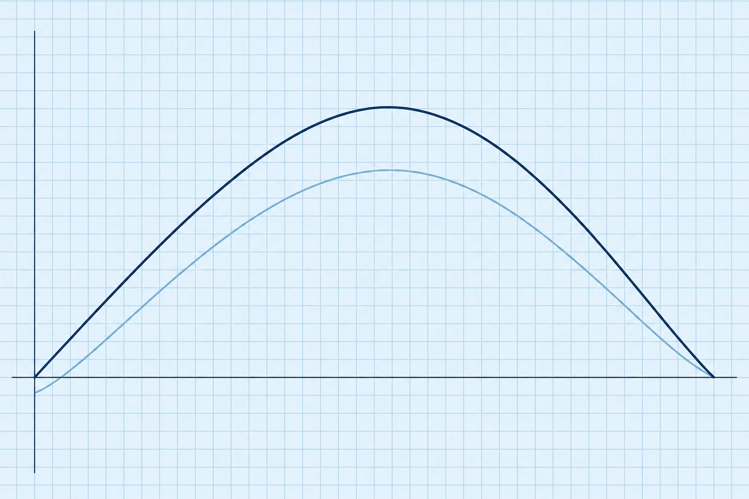
If G lies off the centreline by GGH, the horizontal shift of G, each lever towards that side shrinks by GGH × cos θ: GZ corrected = GZ − GGH × cos θ. The curve now starts below zero. The ship lists to where it crosses zero. She has less maximum GZ, range and area on the listed side.
Negative GM and loll
Negative GM fluid makes upright equilibrium unstable. She can settle at an angle of loll only if GZ recovers through zero with a positive slope before downflooding. Otherwise, capsize may follow. For a wall-sided hull within its validity limits, tan θ = √(2 × |GM| ÷ BM). She can loll to either side. See the trim lesson for safe correction.
Reading the curve
Read GM from the starting slope, then maximum GZ, its angle and GZ at 30°. The angle of vanishing stability (AVS) is the later zero crossing, where GZ changes from positive to negative. Positive GZ extends from the stable zero crossing to AVS; with a list, it does not start upright. Take labelled deck edge immersion and downflooding angle θf from the booklet. A bend alone does not reliably identify deck edge immersion. Openings may immerse while GZ is still positive.
Moments and energy
GZ × Δ gives the righting moment in t·m. Multiply Δ by the area under the corrected GZ curve from stable equilibrium to the chosen heel, using radians. This gives dynamical stability: the work needed to heel the ship slowly, in t·m·rad. Start at 0° for an upright stable ship, or at the stable zero-GZ crossing for a listed or lolling ship. This ideal calculation assumes no downflooding. The IS Code area checks follow in the next lesson.
Key figures
- Free surface
- KG fluid = KG + ΣFSM ÷ Δ; lever loss = FSC × sin θ
- List correction
- GZ corrected = GZ − GGH × cos θ
- Loll (wall-sided)
- tan θ = √(2 × |GM| ÷ BM)
- Dynamical stability
- Δ × GZ area from stable equilibrium (t·m·rad)
- Downflooding angle θf
- Heel where openings that cannot close weathertight immerse
Worked example: correcting the curve for a list
- Data: the GZ table from the cross-curves example, with G 0.08 m to port (GGH = 0.08 m). — A tank imbalance has moved G off the centreline.
- Work out 0.08 × cos θ: 0.080, 0.079, 0.075, 0.069, 0.061, 0.051 m at 0–50°. — The loss is largest near upright.
- Subtract: corrected GZ = −0.080, 0.018, 0.160, 0.336, 0.363, 0.245 m. — These are the levers for heel to port.
- Read the list: the curve crosses zero at about 8° to port. — Check: tan θ = 0.08 ÷ 0.55, θ ≈ 8.3°.
- Compare: maximum GZ to port drops from about 0.42 m to about 0.36 m. — Less reserve on the listed side; correct the list before sea.
Remember
- Correct for free surface first: use the fluid KG, or the booklet's own method.
- An off-centre G subtracts GGH × cos θ from every lever on the listed side.
- Negative GM makes upright unstable; loll needs a stable nonzero GZ crossing.
- Read maximum GZ, its angle, GZ at 30°, AVS, deck edge immersion and θf.
- Dynamical stability = Δ × GZ area from stable equilibrium to the chosen heel; use radians.
Common mistakes
Wrong: Correct a list by subtracting GGH × sin θ.
Right: The lever lost to an off-centre G is GGH × cos θ: largest upright, smaller at large heel.
Wrong: A ship lying at 8° with negative GM has a list.
Right: That is loll. A list comes from an off-centre G with positive GM; loll from negative GM.
Wrong: The AVS is the limit to watch for flooding.
Right: Water can enter through openings at θf, often well before AVS. Read both.
Worked case
Leaving port, your ship lies 7° to starboard. There is no off-centre weight in the plan. She rolls slowly and once leans 7° to port instead. The calculation shows a slack double bottom and slack deep tanks. What is happening?
Show the answer
The change of side without a weight shift points to loll rather than a list. Check the calculated GM fluid and tank states: negative GM makes upright equilibrium unstable. Do not sail until the condition meets the approved stability criteria. Follow the trim lesson and approved onboard instructions for safe correction.
Practice question
GZ at 30° is 0.405 m with G on the centreline. G then moves 0.08 m off the centreline. What is GZ at 30° towards the listed side?
- 0.37 m
- 0.47 m
- 0.41 m
- 0.34 m
Show the answer
Answer: D. 0.405 − 0.08 × cos 30° = 0.405 − 0.069 ≈ 0.34 m. 0.37 m wrongly uses sin 30°.
4 · IS Code criteria
The 2008 IS Code general criteria and the area check
Part A 2.2 sets six numbers that every loading condition must meet. You check them with GZ values and Simpson's rules.
Where the rules sit
The 2008 IS Code, resolution MSC.267(85), has a mandatory Part A and a recommendatory Part B. SOLAS and the 1988 Load Line Protocol make Part A compulsory for cargo and passenger ships of 24 m and over. Part A 2.1.1–2.1.2 require the loading-condition and free-surface provisions they reference in Part B. Amendments in force since 1 January 2020 (MSC.413(97)) added rules for towing, lifting and anchor handling; the general criteria stayed the same.
The general criteria
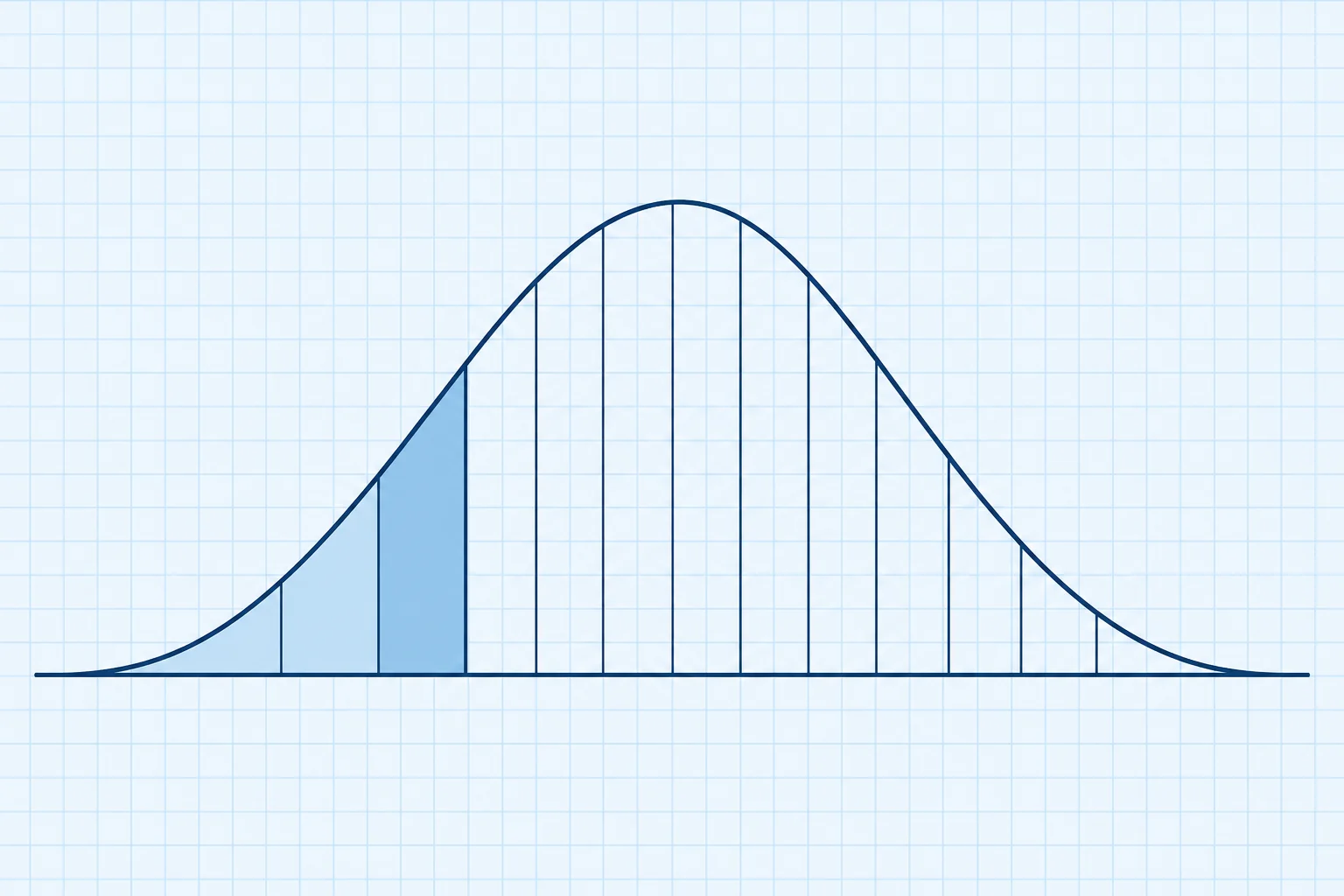
Part A 2.2 asks, with free surface included: area under GZ up to 30° at least 0.055 m·rad; up to 40°, or θf if less, at least 0.090 m·rad; between 30° and 40°, or θf, at least 0.030 m·rad; GZ at least 0.20 m at 30° or more; maximum GZ at 25° or more; and initial GM at least 0.15 m.
Why radians
Area is lever times angle, so the angle must be in radians: 10° = 0.1745 rad. An area worked in metre-degrees is 57.3 times too large and seems to pass everything. Convert the angle step h to radians before you start.
Simpson's rules
Use GZ at equal steps h. Simpson's first rule needs an even number of steps: area = h ÷ 3 × (y0 + 4y1 + 2y2 + 4y3 + y4). Simpson's second rule suits three steps: area = 3h ÷ 8 × (y0 + 3y1 + 3y2 + y3). With 10° steps, use the first for 0–40° and the second for 0–30°. Subtract for 30–40°.
Every condition
The four standard cargo-ship cases are fully loaded departure and ballast departure, both with full fuel and stores, and corresponding arrivals with 10% remaining. In the fully loaded cases, cargo is homogeneously distributed: spread evenly through the cargo spaces. Also check intermediate voyage stages. Fuel use, tank changes and free surface may make one of those stages worse than departure or arrival. Use the approved booklet or loading computer and retain the required safe margin.
Key figures
- Area 0–30°
- At least 0.055 m·rad
- Area 0–40° (or θf)
- At least 0.090 m·rad
- Area 30–40° (or θf)
- At least 0.030 m·rad
- GZ at 30° or more
- At least 0.20 m
- Maximum GZ
- At an angle of heel of 25° or more
- Initial GM
- At least 0.15 m, corrected for free surface
Worked example: the Part A 2.2 check
- Data: GZ at 0°, 10°, 20°, 30°, 40° = 0, 0.097, 0.235, 0.405, 0.424 m; θf beyond 40°; GM 0.55 m. — The fluid-KG curve from the cross-curves example.
- Step h = 10° = 0.1745 rad. — Areas must come out in m·rad.
- 0–30°, second rule: 3 × 0.1745 ÷ 8 × (0 + 0.291 + 0.705 + 0.405) = 0.092 m·rad. — At least 0.055 m·rad: passes.
- 0–40°, first rule: 0.1745 ÷ 3 × (0 + 0.388 + 0.470 + 1.620 + 0.424) = 0.169 m·rad. — At least 0.090 m·rad: passes.
- 30–40°: 0.169 − 0.092 = 0.077 m·rad. — At least 0.030 m·rad: passes.
- Levers: GZ at 30° is 0.405 m; maximum about 0.42 m near 40°; GM 0.55 m. — ≥ 0.20 m, ≥ 25° and ≥ 0.15 m: all six criteria met. Then check the weather criterion.
Remember
- Part A of the 2008 IS Code is mandatory for cargo and passenger ships of 24 m and over.
- Areas: 0.055 to 30°, 0.090 to 40° or θf, 0.030 between; all in m·rad.
- Levers: GZ ≥ 0.20 m at 30° or more, maximum at ≥ 25°, GM ≥ 0.15 m.
- Work areas with h in radians and Simpson's first or second rule.
- Check every stage of the voyage, with free surface included.
Common mistakes
Wrong: Run Simpson's rule with h = 10.
Right: Convert h to radians, 0.1745 for 10°. Metre-degrees are 57.3 times too large.
Wrong: Always take the second area to 40°.
Right: If θf is below 40°, stop the 0–40° and 30–40° areas at θf.
Wrong: Check only the departure condition.
Right: Fuel burn, ballast changes and slack tanks can make the arrival or a mid-voyage stage the worst.
Worked case
A loading computer printout shows all areas passing, but GZ peaks at 22°. The other levers pass. The second officer says one miss among six does not matter. What do you say?
Show the answer
Every criterion must be met. Part A 2.2.3 requires the maximum GZ at 25° or more. Only the Administration can approve alternative criteria of equivalent safety, and those would be in the approved booklet. If they are not there, the condition does not comply. Change the loading, for example by lowering G or reducing free surface, and recheck before sailing.
Practice question
What minimum area under the GZ curve does Part A 2.2 require up to 30°?
- 0.030 m·rad
- 0.090 m·rad
- 0.055 m·rad
- 0.200 m·rad
Show the answer
Answer: C. 0.055 m·rad to 30°, 0.090 to 40° or θf, and 0.030 between 30° and 40° or θf.
5 · Weather criterion
The weather criterion (IS Code 2.3) at a glance
A beam wind heels the ship, waves roll her to windward, then a gust strikes. The weather criterion checks she has energy to spare.
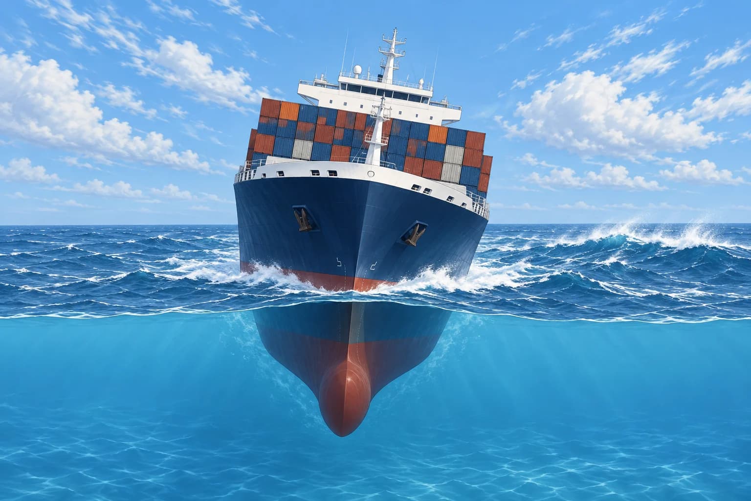
The scenario
Part A 2.3 pictures your ship beam-on to wind and waves. A steady wind heels her to an angle θ0. Waves then roll her to windward by an angle θ1 from there. As she rolls back, a gust strikes. The criterion compares the energy the gust puts in with the righting energy she still has.
The two levers
The steady wind gives lw1 = P × A × Z ÷ (1000 × g × Δ) in metres. P = 504 Pa; A is the above-water side area exposed to wind, including deck cargo, in m²; Δ is displacement in tonnes; g = 9.81 m/s². Z is the vertical separation in metres of the above-water and underwater lateral-area centres. Approximate the latter at half the mean draught below the waterline. The gust lever is lw2 = 1.5 × lw1. Draw both as horizontal lines.
The two tests
First, θ0 must not exceed 16° or 80 % of the deck edge immersion angle, whichever is less. Second, area b must be at least area a. Area a lies between lw2 and GZ from θ0 − θ1 to their first crossing. Area b lies above lw2 from there to θ2: the least of θf, 50° and θc, the second crossing of lw2 with GZ.
Finding the steady heel
Read θ0 at the first stable intersection of lw1 with the GZ curve. Wind and righting moments balance there. Use this angle for the steady-heel limit. The approved booklet supplies θ1; the windward extreme is θ0 − θ1. Bilge keels generally reduce θ1. A shorter rolling period tends to increase the estimate when the other factors stay fixed. GM alone does not determine θ1; use the approved assessment.
What you do on board
The approved booklet shows the result for each condition, or a curve of maximum KG or minimum GM against draught that covers all the criteria. Follow the booklet's KG-limit and free-surface convention at your actual draught and trim. Compare fluid KG only with a limit defined for fluid KG. Changed deck stowage requires a new check using A, Z, Δ and KG; recheck the approved deck-cargo limits.
Key figures
- Wind pressure
- P = 504 Pa (about 26 m/s); less only if approved
- Steady wind lever
- lw1 = P × A × Z ÷ (1000 × g × Δ) (m)
- Gust lever
- lw2 = 1.5 × lw1
- Steady heel θ0
- ≤ 16° or 80 % of deck edge immersion angle, if less
- Energy check
- Area b ≥ area a
- θ2
- Least of θf, 50° and θc (second GZ–lw2 crossing)
Remember
- Steady wind lever lw1, gust lever lw2 = 1.5 × lw1, roll to windward θ1.
- θ0 ≤ 16° or 80 % of deck edge immersion, whichever is less.
- Area b ≥ area a, with b ending at θf, 50° or θc, whichever is least.
- Follow the booklet's KG-limit and free-surface convention at your actual draught and trim.
- Changed deck stowage requires a fresh windage and stability check using A, Z, Δ and KG.
Common mistakes
Wrong: Passing 2.2 means the weather criterion is passed too.
Right: The weather criterion is a separate mandatory check. A high-windage ship can pass 2.2 and fail 2.3.
Wrong: The steady heel limit is always 16°.
Right: It is 16° or 80 % of the deck edge immersion angle, whichever is less.
Wrong: Every maximum KG curve uses the same free-surface convention.
Right: Read the curve's stated free-surface allowance. Compare fluid KG only when the limit is defined for fluid KG.
Worked case
A container feeder has Δ 15,000 t, lateral windage area 2,400 m² and Z 9.0 m. The deck edge immerses at 18°. The planner wants an extra tier on deck. What do the numbers tell you, and what do you check?
Show the answer
lw1 = 504 × 2,400 × 9.0 ÷ (1000 × 9.81 × 15,000) ≈ 0.074 m; lw2 ≈ 0.111 m. The steady heel limit is 80 % of 18° = 14.4°, less than 16°. An extra tier changes windage, displacement and KG; recompute the lever and criterion. Check the KG and deck-cargo limits at actual draught and trim, following the booklet's free-surface convention. Outside those limits, the condition is not approved.
Practice question
The deck edge immerses at 18°. What is the maximum steady wind heel θ0 allowed?
- 16.0°
- 14.4°
- 18.0°
- 12.8°
Show the answer
Answer: B. 80 % of 18° = 14.4°, which is less than 16°. 12.8° wrongly takes 80 % of 16°.